Radio module

a radio module and antenna technology, applied in the direction of antennas, antenna details, elongated active element feed, etc., can solve the problems of increasing the size and cost of the terminal, reducing the impedance and bandwidth, etc., and achieve the effect of widening the bandwidth without increasing the size of the terminal

Inactive Publication Date: 2010-11-02
TOSHIBA CLIENT SOLUTIONS CO LTD
View PDF30 Cites 20 Cited by
  • Summary
  • Abstract
  • Description
  • Claims
  • Application Information

AI Technical Summary

Benefits of technology

[0008]It is an object of the present invention to provide a radio module capable of improving impedance characteristics and radiation characteristics, and widening the bandwidth without increasing the size of a terminal.
[0010]With this arrangement, a current flowing on the ground pattern along the side of the circuit board, in which a radiation of a radio frequency signal is generated, during use of the antenna is partially shunted to the conductor at or near a position spaced apart by a quarter-wavelength from the connection point between the radio circuit and the antenna, i.e., the feed point. This makes it possible to effectively flow a current flowing to the ground pattern of the circuit board to the conductor at a position where the current value is maximum. This can improve the radiation characteristics of the antenna. Since the conductor appears open from the viewpoint of the feed point, the impedance can be increased. When the current flowing on the ground pattern along the side of the circuit board, in which a radiation of a radio frequency signal is generated, is partially shunted to the conductor, a plurality of resonance modes can be generated to widen the bandwidth.
[0011]The conductor is located on a circuit board surface opposing the circuit board surface facing the user during speech communication or on a side surface. The influence of the user on the conductor can be reduced as compared with the case in which the conductor is located on the circuit board surface facing the user. The circuit board surface facing the user during speech communication generally has a narrow mounting space but does not have the conductor, thereby preventing an increase in size of the terminal.
[0013]With this arrangement, similar to the first aspect, a current flowing on the ground pattern along the radiation of a radio frequency signal generation side of the circuit board during use of the antenna is partially shunted to the conductor. This can improve the radiation characteristics of the antenna. The effective electrical length between the feed point and the distal end of the conductor is set to be a half-wavelength of a radio-frequency signal or a value in the neighborhood of it. Hence, the conductor appears open from the viewpoint of the feed point, and the input impedance can be increased. When the current flowing on the ground pattern along the side of the circuit board, in which a radiation of a radio frequency signal is generated, is partially shunted to the conductor, a plurality of resonance modes can be generated to widen the bandwidth. Additionally, similar to the first aspect, when the conductor is located on a circuit board surface opposing the circuit board surface facing the user during speech communication or a side surface, the influence of the user on the conductor can be reduced, thereby preventing an increase in size of the terminal.
[0015]With this arrangement, the following effects can be obtained in addition to the effects obtained according to the first and second aspects. That is, the second antenna to be used for another communication operation can be used as a conductor in radio communication of the first antenna. As a result, a conductor need not be additionally located, thereby preventing an increase in size of the radio module and an increase in mounting density.
[0016]Accordingly, the present invention can provide a radio module capable of improving the impedance characteristics and radiation characteristics, and widening the bandwidth without increasing the size of the terminal.

Problems solved by technology

However, since such built-in antenna is arranged close to the ground pattern of a circuit board accommodated in the housing, the impedance and bandwidth obviously decrease.
Also, when using a monopole antenna, a radiation pattern varies in accordance with the size of the ground pattern of the circuit board, thus posing a problem.
Hence, when the L-shaped plate is located on the circuit board surface facing the user, the circuit board must become large, and this leads to an increase in size and cost of the terminal.

Method used


Image

  • Radio module
  • Radio module
  • Radio module

Examples


first embodiment

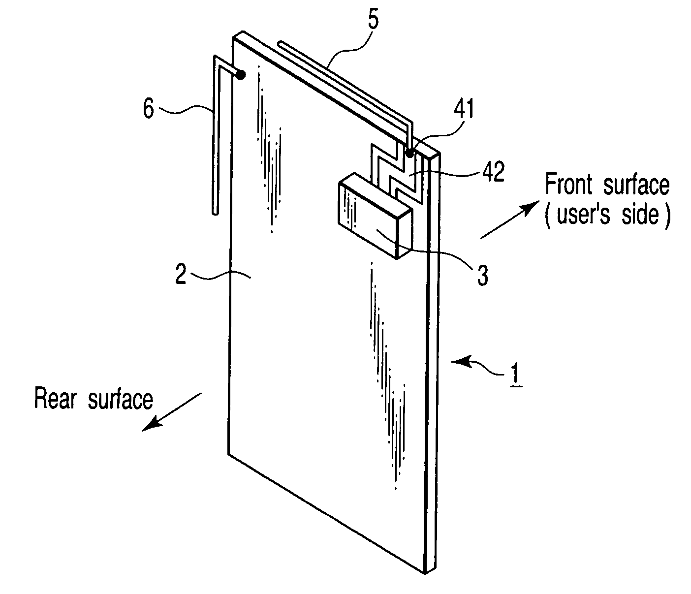
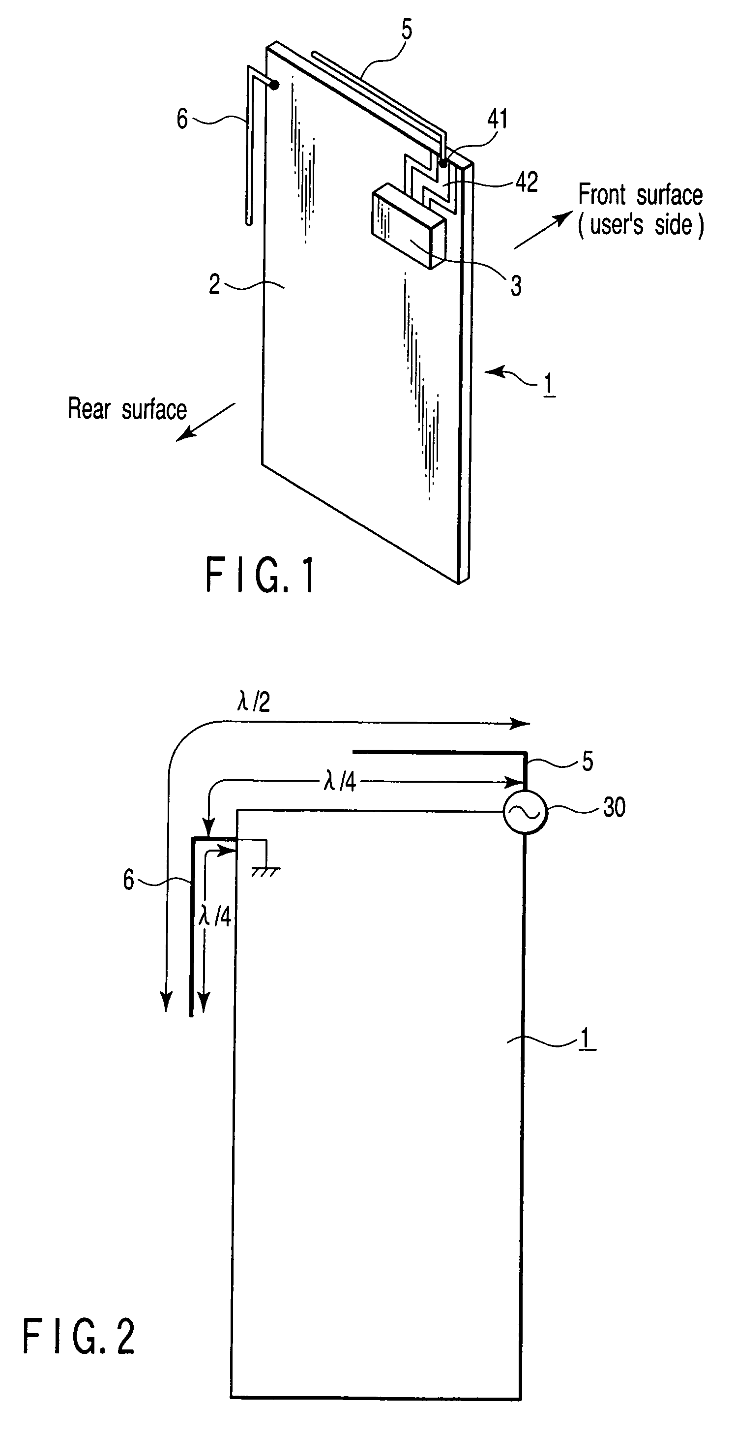
[0054]FIG. 1 is a perspective view showing the arrangement of a radio module for a portable terminal according to the first embodiment of the present invention.

[0055]The radio module is accommodated between the front cover and rear case (both not shown) of a housing of the portable terminal. In this accommodation state, a “front surface” side shown in FIG. 1 is set as a front cover side, i.e., the side facing a user's head during speech communication, and a “rear surface” side shown in FIG. 1 is set as a rear case side.

[0056]The radio module includes a circuit board 1. The circuit board 1 comprises a double-sided printed wiring board having printed wiring patterns on the front and rear surfaces, and a radio circuit 3 is mounted on the rear surface. Additionally, an antenna connection terminal 41 and a signal line pattern 42 which connects this antenna connection terminal with the radio circuit 3 are formed on the rear surface of the circuit board 1, and an antenna 5 is connected to ...

second embodiment

[0069]According to the second embodiment of the present invention, in a radio module such as a radio module installed in a foldable portable terminal in which two circuit board units are connected via a flexible cable or thin coaxial cable, a conductor is grounded on a radiation of a radio frequency signal generation side of the circuit board unit on which a radio circuit and an antenna are mounted, on the extension line of the position of a connector of the cable from the viewpoint of a feed point.

[0070]FIG. 13 is a perspective view showing the arrangement of the radio module according to the second embodiment of the present invention. Note that the same reference numbers as shown in FIG. 1 denote the same parts in FIG. 13. In the radio module according to this embodiment, a first circuit board 1 accommodated in a lower housing and a second circuit board 7 accommodated in an upper housing are connected to each other via a cable 11 and connectors 9 and 10. The connector 9 is located...

third embodiment

[0080]According to the third embodiment of the present invention, a conductor 6 is grounded on a ground pattern 2 via an impedance adjustment circuit.

[0081]FIG. 20 is a perspective view showing the arrangement of a radio module according to the third embodiment of the present invention. Note that the same reference numbers as in FIG. 1 denote the same parts in FIG. 20, and a detailed description thereof will be omitted. An impedance adjustment circuit 12 is mounted on a radiation of a radio frequency signal generation side of a circuit board 1, at a position spaced apart by a quarter-wavelength of a radio-frequency signal from a feed point. The conductor 6 is connected to the ground pattern 2 via the impedance adjustment circuit 12.

(1) Example 1

[0082]As denoted by reference number 12a in FIG. 21, the impedance adjustment circuit 12 comprises an inductor L1. When the conductor 6 is connected to the ground pattern 2 via the inductor L1 as shown in FIG. 21, the effective electrical len...


PUM


Abstract

A conductor is mounted on a circuit board parallel to its side along which a radiation of a radio frequency signal is generated. The proximal end of the L-shaped conductor is electrically connected to a ground pattern formed on the rear surface of a circuit board 1, and the distal end of the L-shaped conductor is open. The position at which the conductor is connected to the ground pattern is set to be a position spaced apart by a quarter-wavelength of a radio-frequency signal from a feed point of an antenna. The total length of the conductor is set to be a half-wavelength of the radio-frequency signal.

Description

CROSS-REFERENCE TO RELATED APPLICATIONS[0001]This application is based upon and claims the benefit of priority from prior Japanese Patent Application No. 2006-188578, filed Jul. 7, 2006, the entire contents of which are incorporated herein by reference.BACKGROUND OF THE INVENTION[0002]1. Field of the Invention[0003]The present invention relates to a radio module having an antenna and, more particularly, to a radio module installed in a radio communication terminal such as a cellular phone, PDA (Personal Digital Assistants), cordless phone, or transceiver which is used in contact with or close to a user.[0004]2. Description of the Related Art[0005]Recently, in a mobile communication terminal represented by a cellular phone, a built-in antenna accommodated in a housing is mainly used. However, since such built-in antenna is arranged close to the ground pattern of a circuit board accommodated in the housing, the impedance and bandwidth obviously decrease. Also, when using a monopole an...

Claims


Application Information

Patent Timeline
Patent Type & Authority Patents(United States)
IPC IPC(8): H01Q1/24
CPCH01Q1/243H01Q9/42
Inventor SATO, KOICHIMIURA, YUSUKE
Owner TOSHIBA CLIENT SOLUTIONS CO LTD
Why Eureka
Try Eureka