Data compression apparatus and data compression program storage medium

a data compression and program storage technology, applied in the field of data compression apparatus and data compression program storage medium, can solve the problems of deterioration of the throughput of the entire compression processing system, and achieve the effects of high image quality, high image quality, and high image quality

Active Publication Date: 2010-11-02
FUJIFILM HLDG CORP +1
View PDF12 Cites 4 Cited by
  • Summary
  • Abstract
  • Description
  • Claims
  • Application Information

AI Technical Summary

Benefits of technology

[0082]According to the data compression apparatus and the data compression program storage medium of the present invention described above, data to be compressed is separated into first data to be compressed, which has been cyclically thinned out, and remaining second data, and lossless compression processing is performed for the first data to be compressed and lossy compression processing is performed for the second data to be compressed. As for the second data to be compressed, a part of original information is lost by lossy compression. However, since correlation between adjacent pixels of a CT image is strong, the image quality of the original image can be kept high even if the second data to be compressed is significantly compressed.
[0083]If the lossy compression section is such that, when compressing the second data to be compressed, switches a compression method according to whether or not the value is between the first data to be compressed, then the image quality can be kept by avoiding compression for such a portion as is not correlated with an adjacent pixel as well as realizing significant compression for such a portion as is correlated with an adjacent pixel.
[0084]If the lossy compression section is such that, when compressing the second data to be compressed, switches a compression method according to whether or not the data corresponds to an edge in the image, then image quality can be kept by avoiding compression for an edge portion as well as realizing significant compression for a non-edge portion.
[0085]If the determination section is such that determines an edge portion based on difference, then edge determination can be performed more easily. Furthermore, if the difference is two-dimensional difference, determination of an edge portion is more accurate.
[0086]If the lossless compression section is provided with a difference generation section and the like, then, at this lossless compression section, new data to be compressed which has been generated from original data to be compressed and the numeric values of which have been offset by an offset section is divided into high-order data and low-order data, and lossless compression processing is performed for them by a high-order data compression section and a low-order data compression section, respectively. Generally, in the case of new data to be compressed to be obtained from CT data, the distribution tendency of numeric values in data is remarkably different in the high-order data and in the low-order data as described later, and therefore, there exist lossless compression processings suitable for the respective data, and a high compression ratio is achieved as a whole by the compression processing according to the present invention. As the lossless compression processing provided for each data, processing by a simple algorithm is applicable. Therefore, the processing time required for the compression processing according to the present invention is short. Thus, according to the lossless compression section provided with the difference generation section and the like, especially preferable lossless compression processing is realized when applied to compression of CT data.
[0087]If the high-order data compression section is provided with a first encoding section, only each numeric value to be compressed are encoded into the numeric value and a value indicating the continuations. Therefore, the situation is avoided that the redundancy degree increases in comparison to original data, and the compression ratio is improved.

Problems solved by technology

However, the compression method such as JPEG requires time for compression processing by software, and this causes deterioration of the throughput of the entire compression processing system.

Method used


Image

  • Data compression apparatus and data compression program storage medium
  • Data compression apparatus and data compression program storage medium
  • Data compression apparatus and data compression program storage medium

Examples


first embodiment

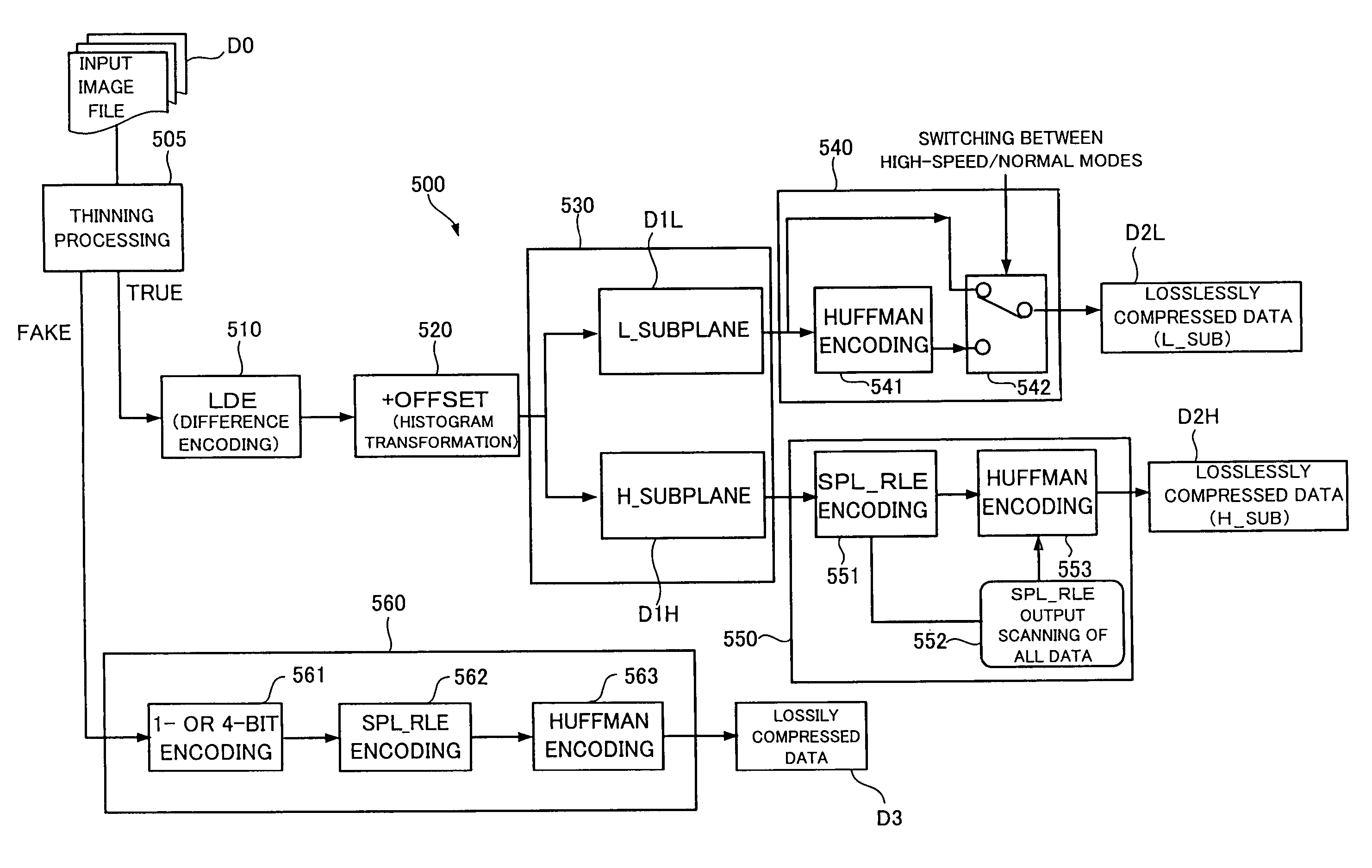
[0119]FIG. 3 is a block diagram showing an image compression apparatus corresponding to the data compression apparatus of the present invention.

[0120]The image compression apparatus 500 shown in FIG. 3 is provided with a thinning processing section 505, a difference encoding section 510, an offset section 520, a plane division section 530, an L plane compression section 540, an H plane compression section 550 and a fake pixel compression section 560. The details of each of the sections 505 to 560 will be described later. The flow of image data in this image compression apparatus 500 is as shown below.

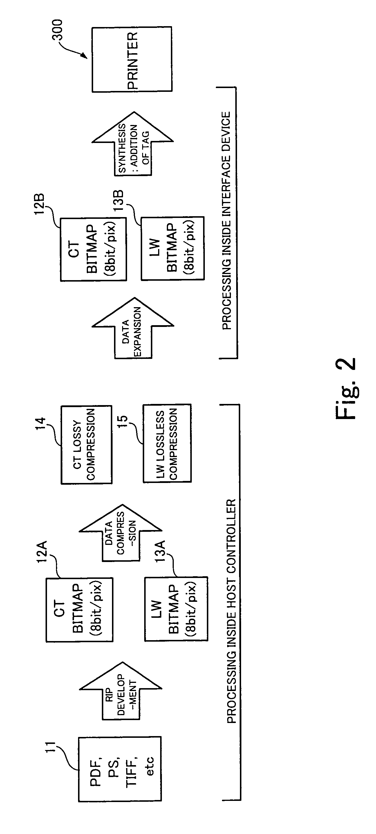
[0121]An input image file D0 (in this embodiment, a file in which the CT data 12A developed in a bitmap is stored, as shown in FIG. 2) is inputted to the thinning processing section 505 of the image compression apparatus 500 shown in FIG. 3, and true pixel data corresponding to cyclic pixel portions in the image is thinned from the image data. The data left after the thinning is to be f...

second embodiment

[0227]FIG. 19 is a block diagram showing an image compression apparatus corresponding to the data compression apparatus of the present invention.

[0228]The image compression apparatus 500′ shown in FIG. 19 is provided with a thinning processing section 505, a difference encoding section 510′, an offset section 520, an edge detection section 525, a plane division section 530, an L plane compression section 540, an H plane compression section 550 and a fake pixel compression section 560′.

[0229]In this second embodiment, true pixel data is inputted to the difference encoding section 510′, and two-dimensional difference encoding processing is performed, that is, processing for determining, for each numeric value of a sequence of numeric values constituting the inputted data, two-dimensional difference based on multiple numeric values adjacent to the numeric value in multiple directions when seen on the image and generating image data configured by a sequence of eight-bit numeric values i...

third embodiment

[0256]FIG. 22 is a block diagram showing an image compression apparatus corresponding to the data compression apparatus of the present invention.

[0257]The image compression apparatus 1500 shown in FIG. 22 is provided with a first lossless compression processing section 1501, a second lossless compression processing section 1502, a lossy compression processing section 1503 and a determination section 1504. The details of each of the sections 1501 to 1503 will be described later. The flow of image data in this image compression apparatus 1500 is as shown below.

[0258]An input image file D0 (in this embodiment, a file in which the CT data 12A or the LW data 13A developed in a bitmap is stored as shown in FIG. 2) is inputted to the first lossless compression processing section 1501 of the image compression apparatus 1500 shown in FIG. 22. At this first lossless compression processing section 1501, first lossless compression processing is performed for image data in the input image file D...


PUM


Abstract

There are provided a data compression apparatus and a data compression program capable of performing new and preferable compression processing applicable to compression of CT data. They are provided with: a thinning processing section which creates, by cyclically thinning out a numeric value from the sequence of numeric values constituting the data to be compressed, first data to be compressed which is constituted by a sequence of the numeric values taken out from the data to be compressed by the thinning out, and second data to be compressed which is constituted by a sequence of the remaining numeric values; a lossless compression section which performs lossless compression processing for the first data to be compressed which has been created by the thinning processing section; and a lossy compression section which performs lossy compression processing for the second data to be compressed which has been created by the thinning processing section.

Description

BACKGROUND OF THE INVENTION[0001]1. Field of the Invention[0002]The present invention relates to a data compression apparatus which compresses data such as image data and a data compression program storage medium in which a data compression program for causing an information processing apparatus such as a computer to operate as the data compression apparatus is stored.[0003]2. Description of the Related Art[0004]There has been broadly adopted a technique for compressing data such as image data to reduce storage capacity or communication traffic.[0005]For example, in Japanese Patent Laid-Open No. 05-328142, the following technique is disclosed. When representative colors are selected from an original image to configure a CLUT (color lookup table), color numbers are assigned so that a sequence of color numbers may indicate color data of close values. Then, a bitmap in accordance with the CLUT is created, and difference between color numbers of adjacent pixels is obtained. When the val...

Claims


Application Information

Patent Timeline
Patent Type & Authority Patents(United States)
IPC IPC(8): G06K9/36
CPCH04N1/41H04N19/13H04N19/63H04N19/1883H04N19/93
Inventor SUGITA, YUKIO
Owner FUJIFILM HLDG CORP
Why Eureka
Try Eureka