Method for manufacturing a nozzle plate
a manufacturing method and nozzle plate technology, applied in the direction of manufacturing tools, conductive pattern formation, machines/engines, etc., can solve the problems of difficult to constantly form the end section of the nozzle hole among multiple plate members, and difficult to accurately form the end section of the nozzle hol
- Summary
- Abstract
- Description
- Claims
- Application Information
AI Technical Summary
Benefits of technology
Problems solved by technology
Method used
Image

Examples
first embodiment
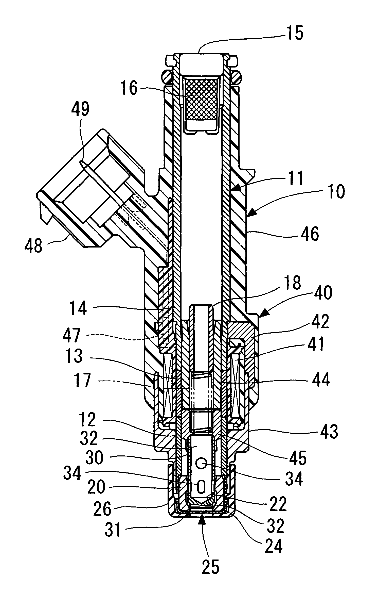
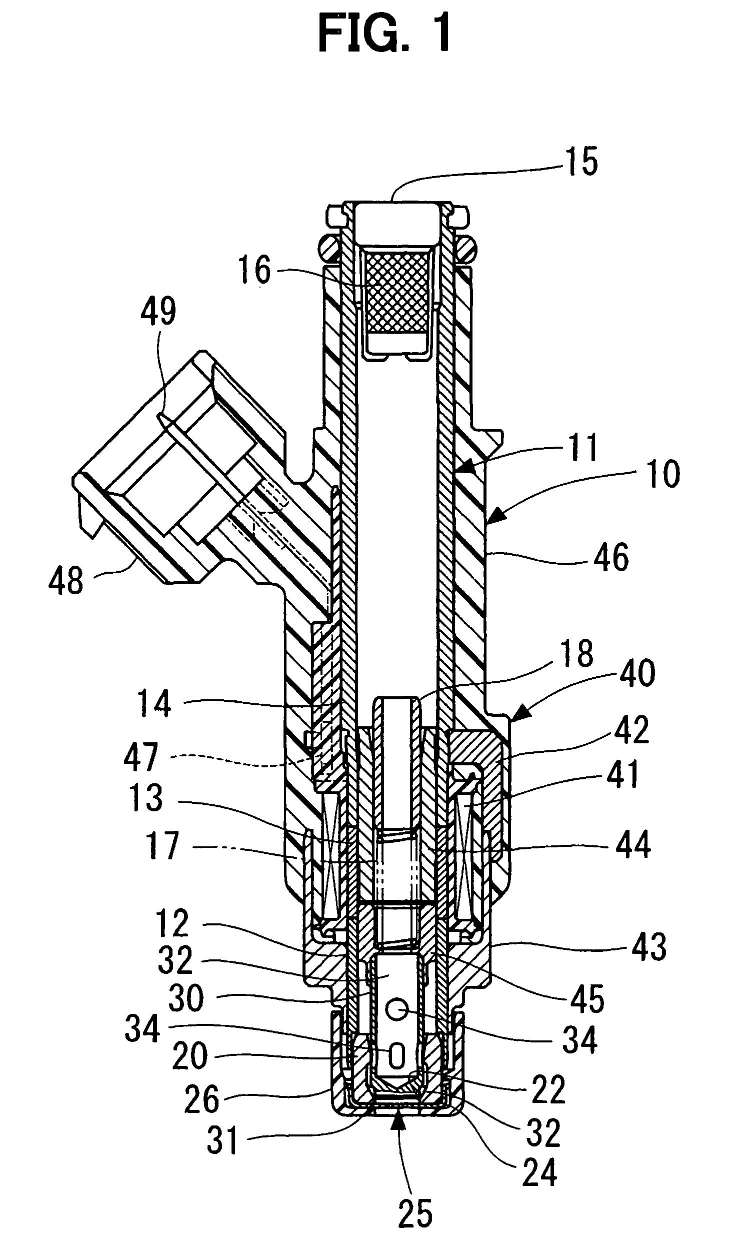
[0017]As shown in FIG. 1, an injector 10 is provided to an internal combustion engine such as a gasoline engine for injecting fuel into intake air drawn into a combustion chamber of the engine. The fuel serves as fluid. The injector 10 may be provided to a direct-injection gasoline engine, in which fuel is directly injected into a combustion chamber. Alternatively, the injector 10 may be provided to another engine such as a diesel engine. The injector 10 may spray fluid other than fuel. For example, the injector 10 may spray ink.
[0018]The injector 10 includes an accommodating pipe 11. The accommodating pipe 11 is in a substantially cylindrical shape having a thing wall. The accommodating pipe 11 includes a first magnetic portion 12, a non-magnetic portion 13, and a second magnetic portion 14. The non-magnetic portion 13 restricts the first magnetic portion 12 and the second magnetic portion 14 from causing magnetic short circuit therebetween. The accommodating pipe 11 has one end de...
second embodiment
[0043]In this second embodiment, as shown in FIGS. 5A, 5B, the plate member 50 is applied with the punch 52, and thereby provided with the small hole 51. That is, forming of the small hole 51 in the plate member 50 is similar to that in the first embodiment. In this second embodiment, the small hole 51 is formed in the plate member 50, and subsequently, as shown in FIG. 5C, the downstream axial end surface 54 of the plate member 50 with respect to the hammering direction of the punch 52 is grinded using a grinding device 57 such as a brush and a grindstone. The plate member 50 is grinded using the grinding device 57, so that a burr 55, which protrudes from the axial end surface 54 to the opposite side of the axial end surface 53, is trimmed. Furthermore, a relatively large burr 55 can be also removed by grinding using the grinding device 57. However, it is difficult to remove a burr 55 protruding radially inside the small hole 51 and a relatively small burr 55, even grinding using t...
PUM
| Property | Measurement | Unit |
|---|---|---|
| thickness | aaaaa | aaaaa |
| diameter | aaaaa | aaaaa |
| inner diameter | aaaaa | aaaaa |
Abstract
Description
Claims
Application Information