Seal assembly for reducing fluid loss from transmission pump

a transmission pump and fluid loss technology, applied in the direction of fluid couplings, gearings, liquid fuel engines, etc., can solve the problems of reducing the efficiency of the transmission, and achieve the effect of minimizing frictional losses, and reducing the loss of the transmission pump

Active Publication Date: 2010-11-09
GM GLOBAL TECH OPERATIONS LLC
View PDF8 Cites 1 Cited by
  • Summary
  • Abstract
  • Description
  • Claims
  • Application Information

AI Technical Summary

Benefits of technology

[0004]An improved seal assembly is provided that: minimizes loss of transmission pump pressure by controlling fluid flow past the torque converter hub bushing to satisfy bushing lubrication requirements without allowing excess fluid flow that unnecessarily diminishes pump pressure, while also minimizing frictional losses and reducing assembly time and error. The seal assembly includes a rigid carrier adapted to fit between the pump body member and the torque converter hub. An elastomeric lip extends from the rigid carrier. A contact layer is connected to the elastomeric lip and is configured to sealingly contact the torque converter hub. The contact layer is harder than the elastomeric lip, and therefore reduces friction losses at the rotating torque converter hub. Notably, the elastomeric lip and contact layer are integrally connected with the rigid carrier, whether by overmolding, adhesion, or other known methods, and there is thus no frictional loss between the lip and the rigid carrier. The rigid carrier has an orifice positioned in fluid connection with the gap and sized to control (i.e., minimize) the flow of fluid from the pump cavity through the gap, to minimize pump pressure loss. The rigid carrier also has vent openings that permit fluid that has flowed through the orifice to return to a sump. Preferably, a seal member such as another elastomeric lip or an O-ring is operatively connected to the rigid carrier to sealingly contact the pump body member, thus partially defining a pressurized cavity on a side of the rigid carrier adjacent the bushing, upstream of the orifice.

Problems solved by technology

Loss of pump pressure through leakage reduces the efficiency of the transmission.

Method used


Image

  • Seal assembly for reducing fluid loss from transmission pump
  • Seal assembly for reducing fluid loss from transmission pump
  • Seal assembly for reducing fluid loss from transmission pump

Examples


Embodiment Construction

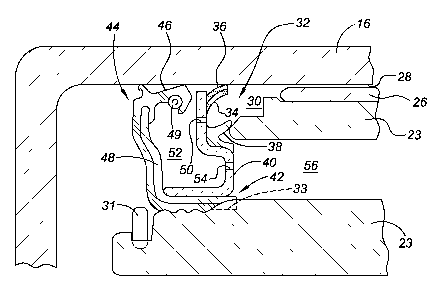
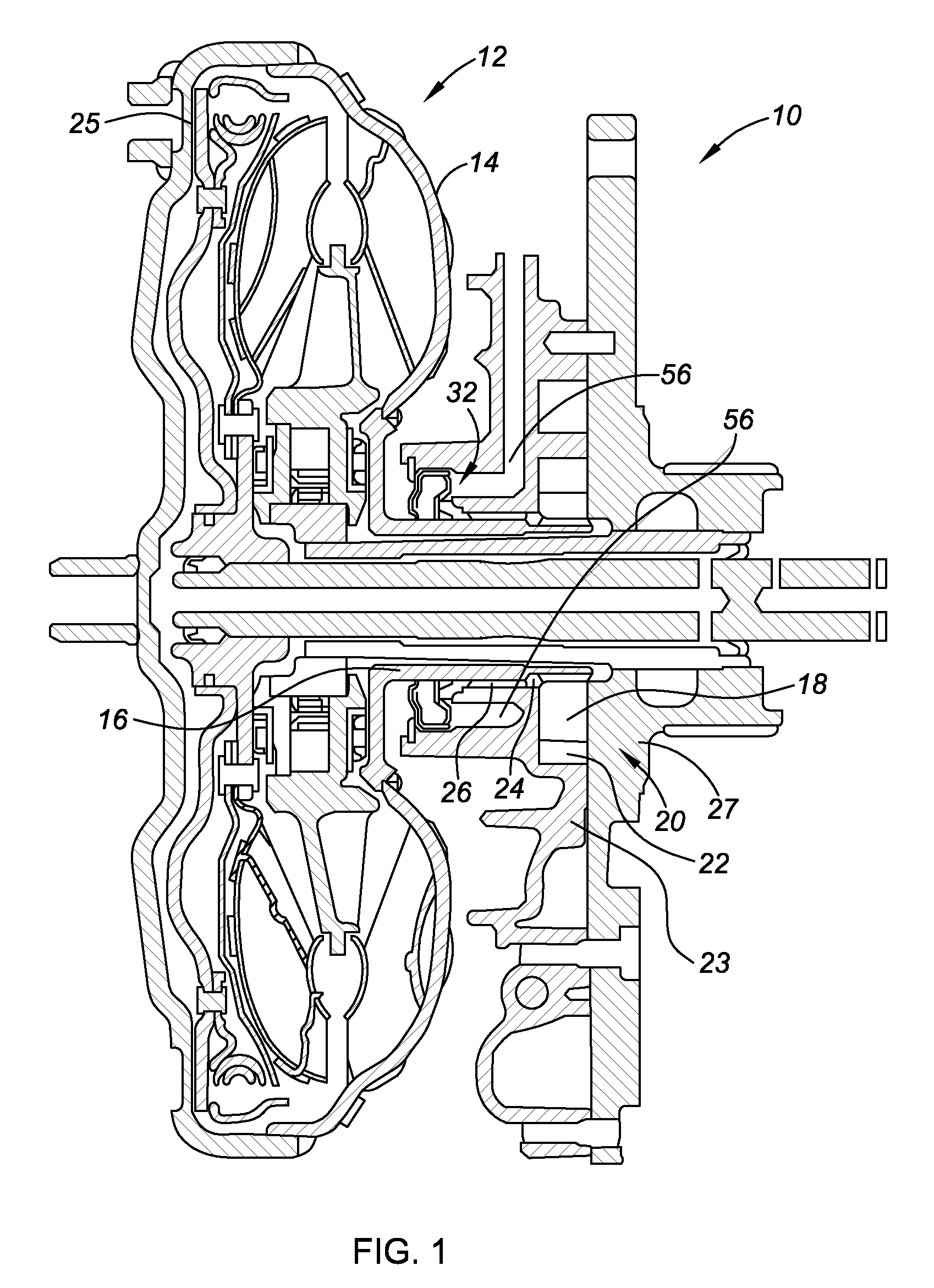
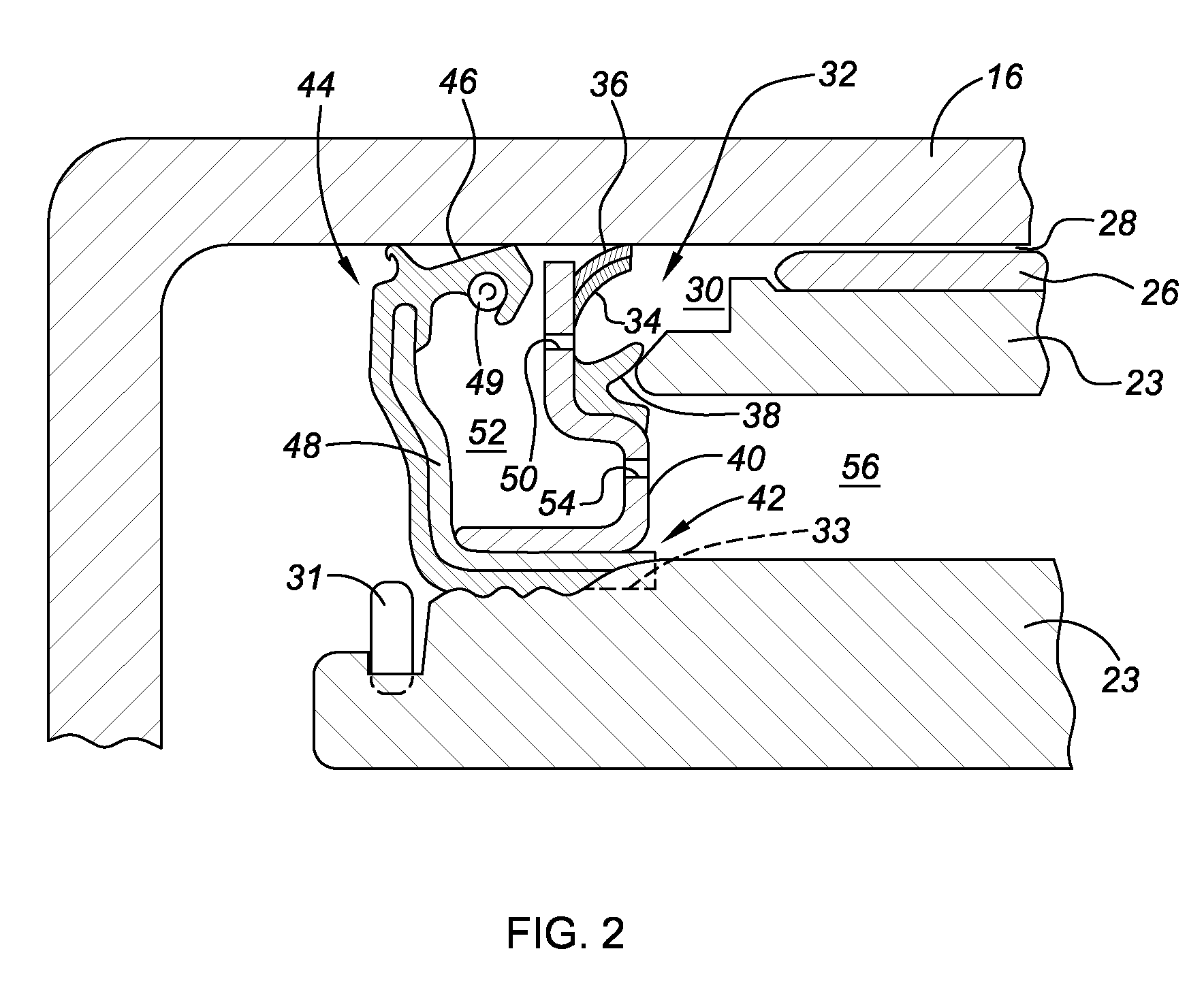
[0010]Referring to FIG. 1, a transmission 10 includes a torque converter assembly 12 with a rotor 14 driven by an engine or other power source (not shown) and a torque converter hub 16 connected for rotation with the rotor 14, as is known. The torque converter hub 16 drivingly engages a pump gear 18 of a transmission pump 20 to pressurize fluid which is transferred from discharge pump cavity 22, partially defined by a stationary pump body member 23, to various components of the transmission 10 to meet hydraulic power requirements. A cavity 24 is primarily filled from oil transfer channels in the pump 20 that provide controlled supply pressure to a torque converter clutch 25 or, when the torque converter clutch 25 is off, lubrication flow and pressure. The cavity 24 can also fill with pressurized fluid leakage past the pump gear 18. A bushing 26 is press fit between the pump body member 23 and the torque converter hub 16 to permit rotation of the torque converter hub 16 relative to t...


PUM


Abstract

An improved seal assembly is provided that minimizes loss of transmission pump pressure by controlling fluid flow past a torque converter hub bushing to meet bushing lubrication requirements without unnecessarily diminishing pump pressure and while also minimizing frictional losses. The seal assembly includes a rigid carrier adapted to fit between a pump body member and the torque converter hub. An elastomeric lip extends from the rigid carrier. A contact layer is connected to the elastomeric lip and configured to sealingly contact the torque converter hub. The contact layer is integral with and harder than the elastomeric lip, therefore minimizing frictional losses.

Description

CROSS-REFERENCE TO RELATED APPLICATIONS[0001]This application claims the benefit of U.S. Provisional Application No. 60 / 939,916 filed May 24, 2007, which is hereby incorporated by reference in its entirety.TECHNICAL FIELD[0002]The invention relates to a seal assembly for a transmission pump.BACKGROUND OF THE INVENTION[0003]Hydraulic transmission pumps are typically powered by a hub attached to a torque converter which in turn is driven by engine output. A bushing is positioned between the torque converter hub and a stationary body member of the pump to permit relative rotation of the torque converter hub. The transmission pump provides pressurized fluid to meet the cooling, lubrication, and clutch apply pressure requirements of the transmission. Loss of pump pressure through leakage reduces the efficiency of the transmission. Pump seals are typically provided to maintain pump pressure. The bushing must be lubricated, so some of the pressurized fluid is typically directed through a g...

Claims


Application Information

Patent Timeline
Patent Type & Authority Patents(United States)
IPC IPC(8): F16D31/02
CPCF01C19/005F04C15/0038F16H57/0434F16J15/3232F16J15/3252F16J15/54F04C2/10F16H41/24
Inventor OLENZEK, RICHARD F.COLEMAN, STEVEN A.
Owner GM GLOBAL TECH OPERATIONS LLC
Why Eureka
Try Eureka