Fuel supply apparatus

a technology of fuel supply and fuel tank, which is applied in the direction of braking system, process and machine control, instruments, etc., can solve the problems of clogging of filters, excessive fuel flow, and melting of solidified fuel, so as to reduce the clogging of filters, increase the recirculation fuel pressure, and complicate the structure

Active Publication Date: 2010-11-09
DENSO CORP
View PDF5 Cites 13 Cited by
  • Summary
  • Abstract
  • Description
  • Claims
  • Application Information

AI Technical Summary

Benefits of technology

[0005]The present invention is made in view of the above matters, and it is an object of the present invention to provide a fuel supply apparatus capable of reducing a clogging of a filter due to a solidified fuel without increasing a number of parts, complicating a structure, and increasing a recirculated fuel pressure.
[0006]According to the present invention, a filter is provided between an electric pump suctioning a fuel from a fuel tank and a mechanical pump pressurizing the fuel suctioned by the electric pump. A branch passage branched from a recirculation passage is fluidly connected to an inlet of the filter. An excessive fuel flows in the recirculation passage. A control unit controls an operation of the electric motor to reduce the fuel quantity discharged from the electric pump to the filter when a pressure loss of the fuel in the filter is increased. The mechanical pump continues to be driven without respect to the fuel quantity discharged from the electric pump. If the fuel quantity discharged from the electric pump is decreased, a suction pressure is generated at an inlet portion of the mechanical pump. Thereby, the fuel recirculated from the branch passage to the fuel tank is introduced into the filter. As the result, a relatively high temperature fuel which should be recirculated into the fuel tank is introduced into the filter so that the solidified fuel causing a clogging of the filter is melted. That is, by reducing the fuel quantity discharged from the electric pump, the mechanical pump introduces the high temperature fuel into the filter without increasing the recirculated fuel pressure and heating the filter. Thus, a clogging of the filter due to the solidified fuel can be reduced without increasing the number of parts, complicating the structure, and increasing the pressure of the recirculated fuel.
[0007]According to another aspect of the present invention, the control unit controls the fuel quantity discharged from the electric pump based on the fuel temperature and the fuel pressure. When the fuel temperature is lower than a lower limit temperature and the fuel pressure is lower than the lower limit pressure, the fuel quantity discharged from the electric pump is reduced. When the fuel temperature is low, there is a possibility that a component contained in the fuel of which melting point is low is solidified. Further, when the fuel pressure passing through the filter is low, there is a possibility that the filter is clogged. When the fuel temperature and the fuel pressure are low, the control unit determines that the filter is clogged due to the solidified fuel and reduces the fuel quantity discharged from the electric pump. Thereby, the fuel recirculated from the branch passage is introduced into the filter by a suction pressure of the mechanical pump. Thus, a clogging of the filter due to the solidified fuel can be reduced with a simple configuration.
[0008]According to another aspect of the present invention, the control unit outputs a stop command to stop the electric pump, or a flow rate reducing command to reduce the fuel quantity discharged from the electric pump. The fuel quantity discharged from the electric pump is varied based on a clogging degree of the filter. Thus a clogging of the filter due to a solidified fuel can be reduced.
[0009]According to another aspect of the present invention, the branch passage is provided with a check valve or a restriction. Usually, the fuel suctioned by the electric pump is introduced from the fuel tank to the filter. When the filter is clogged and the fuel pressure at the inlet of the mechanical pump is decreased, the recirculated fuel flows into the filter through the check valve or the restrictor. Thus, a clogging of the filter due to a solidified fuel can be reduced.
[0010]According to another aspect of the present invention, the fuel supply apparatus is further provided with a bypass passage. The mechanical pump can suction the fuel from the fuel tank through the bypass passage bypassing the electric pump. When the fuel flow rates suctioned from the branch passage is insufficient, the fuel is supplied through the bypass passage. Further, the bypass passage is provided with a check valve. If the fuel quantity discharged from the mechanical pump is insufficient, the fuel is suctioned from the fuel tank through the bypass passage. Thus, the fuel quantity supplied from the mechanical pump can be maintained.

Problems solved by technology

An excessive fuel flows in the recirculation passage.
As the result, a relatively high temperature fuel which should be recirculated into the fuel tank is introduced into the filter so that the solidified fuel causing a clogging of the filter is melted.
Further, when the fuel pressure passing through the filter is low, there is a possibility that the filter is clogged.
When the fuel temperature and the fuel pressure are low, the control unit determines that the filter is clogged due to the solidified fuel and reduces the fuel quantity discharged from the electric pump.

Method used


Image

  • Fuel supply apparatus
  • Fuel supply apparatus
  • Fuel supply apparatus

Examples


first embodiment

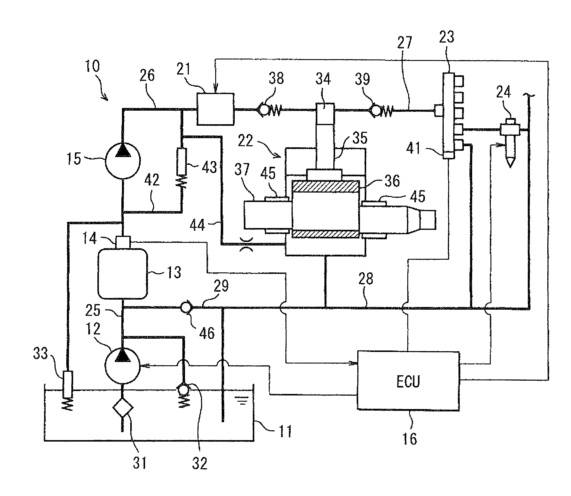
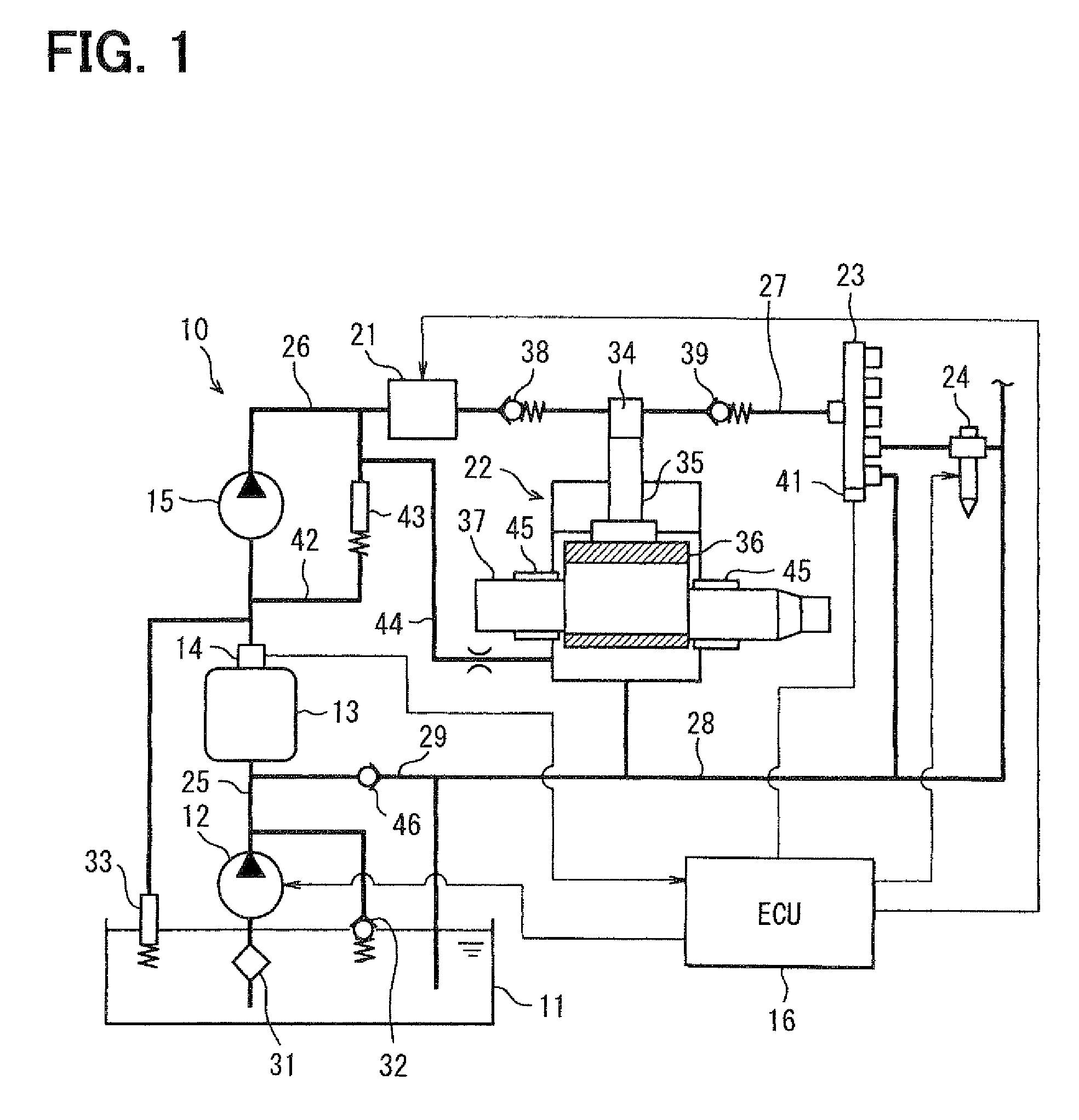
[0018]FIG. 1 is a schematic view showing a fuel supply apparatus according to a first embodiment. A fuel supply apparatus 10 is applied to a common-rail type fuel injection system supplying fuel to a diesel engine (not shown). The fuel supply apparatus 10 is provided with a fuel tank 11, an electric pump 12, a filter 13, a sensor portion 14, a mechanical pump 15, and an electronic control unit (ECU) 16. The fuel injection system is further provided with a flow controller 21, a supply pump 22, a common rail 23, and a fuel injector 24. Further, the fuel supply apparatus 10 is provided with a suction passage 25 fluidly connecting the fuel tank 11 and the filter 13, a supply passage 26 fluidly connecting the filter 13 and the supply pump 22, a high-pressure passage 27 fluidly connecting the supply pump 22 and the common rail 23, a recirculation passage 28 fluidly connecting the supply pump 22, the common rail 23, the fuel injector 24 and the fuel tank 11, and a branch passage 29 branche...

second embodiment

[0036]FIG. 3 is a schematic view showing a fuel supply apparatus according to a second embodiment. As shown in FIG. 3, the fuel supply apparatus 10 is provided with a bypass passage 50 and a fourth check valve 51. The bypass passage 50 fluidly connects the fuel tank 11 and the inlet side of the filter 13 in the suction passage 25. The bypass passage 50 is provided with a suction filter 53 at its end in the fuel tank 11. The fourth check valve 51 is provided in the bypass passage 50. The fourth check valve 51 allows a fuel flow from the fuel tank 11 to the filter 13, and restricts a fuel flow from the filter 13 to the fuel tank 11. The check valve 51 may be disposed outside of the fuel tank 11.

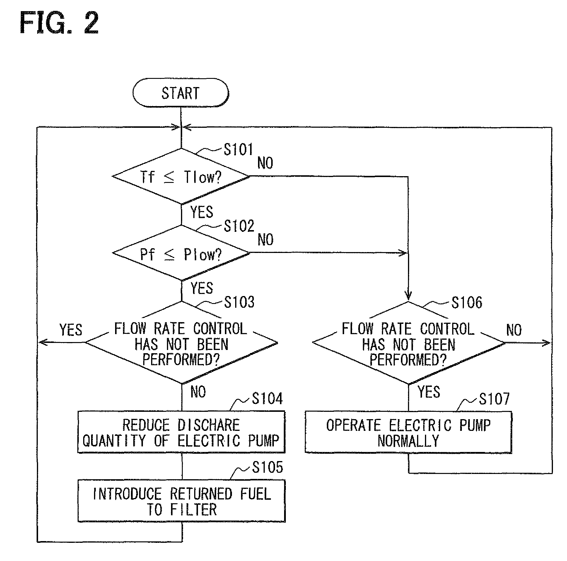
[0037]As described above, when the fuel temperature and the fuel pressure passing through the filter 13 drop, the rotational speed of the electric pump 12 is decreased or the electric pump 12 is stopped. The fuel in the branch passage 29 is introduced into the filter 13 by a suction operation o...


PUM


Abstract

An ECU reduces a fuel flow rate discharged from an electric pump to the filter when a fuel temperature and a fuel pressure in the filter detected by a sensor portion drop. Since a mechanical pump continues to be driven without respect to the fuel quantity discharged from the electric pumps when the fuel flow rate discharged from the electric pump is decreased, a suction pressure is generated at an inlet of the filter. The fuel in a recirculation passage is introduced into the filter through a branch passage. As the result, relatively high temperature fuel is introduced into the filter to melt a solidified fuel causing a clogging of the filter.

Description

CROSS-REFERENCE TO RELATED APPLICATION[0001]This application is based on Japanese Patent Application No. 2008-128320 filed on May 15, 2008, the disclosure of which is incorporated herein by reference.FIELD OF THE INVENTION[0002]The present invention relates to a fuel supply apparatus capable of reducing a clogging of a filter due to a solidified fuel.BACKGROUND OF THE INVENTION[0003]Light oil, which is used for a diesel engine as fuel, includes components that are solidified when temperature drops. The solidified fuel causes a clogging of a filter. The filter captures foreign objects contained in the fuel. High temperature fuel which becomes excessive in a common rail or a fuel injector is recirculated into an inlet of the filter to melt the solidified fuel. Alternatively, the solidified fuel is heated by a heater to be melted.[0004]However, in a case that a filter is disposed at an outlet of a fuel pump, the pressure of fuel discharged by the fuel pump is higher than that of fuel r...

Claims


Application Information

Patent Timeline
Patent Type & Authority Patents(United States)
IPC IPC(8): F02M37/22F02M37/40
CPCF02M37/0047F02M37/22F02M37/40
Inventor NARISAKO, HIDEKISHINOHARA, YUKIHIROKIKUTANI, TAKASHIYONEMOTO, TOSHIYUKI
Owner DENSO CORP
Why Eureka
Try Eureka