Door/gate monitoring sensor device

a technology for monitoring sensors and doors, applied in distance measurement, surveying and navigation, instruments, etc., can solve problems such as difficult or even impossible to determine the correct distance from the sensor to the reflection surface, and disrupt the principle, so as to achieve less susceptible to interference

Active Publication Date: 2010-11-09
CEDES AG
View PDF23 Cites 24 Cited by
  • Summary
  • Abstract
  • Description
  • Claims
  • Application Information

AI Technical Summary

Benefits of technology

[0005]The invention is based on the object of extending the field of use of sensors of the type described in the introduction, in particular of being able to operate them such that they are less susceptible to interference.

Problems solved by technology

This principle may be disrupted if a further sensor likewise emits light which is misinterpreted when evaluating the sensor in question.
As a result, it may become difficult or even impossible to determine a correct distance from the sensor to a reflection surface.

Method used


Image

  • Door/gate monitoring sensor device
  • Door/gate monitoring sensor device
  • Door/gate monitoring sensor device

Examples


Embodiment Construction

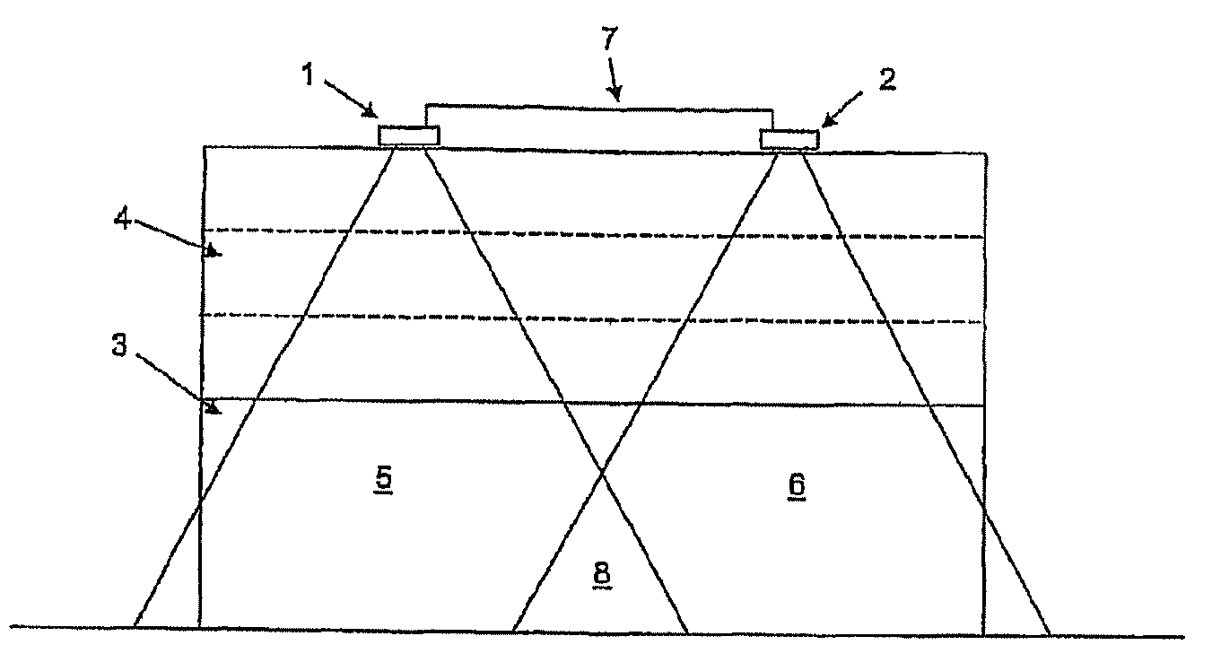
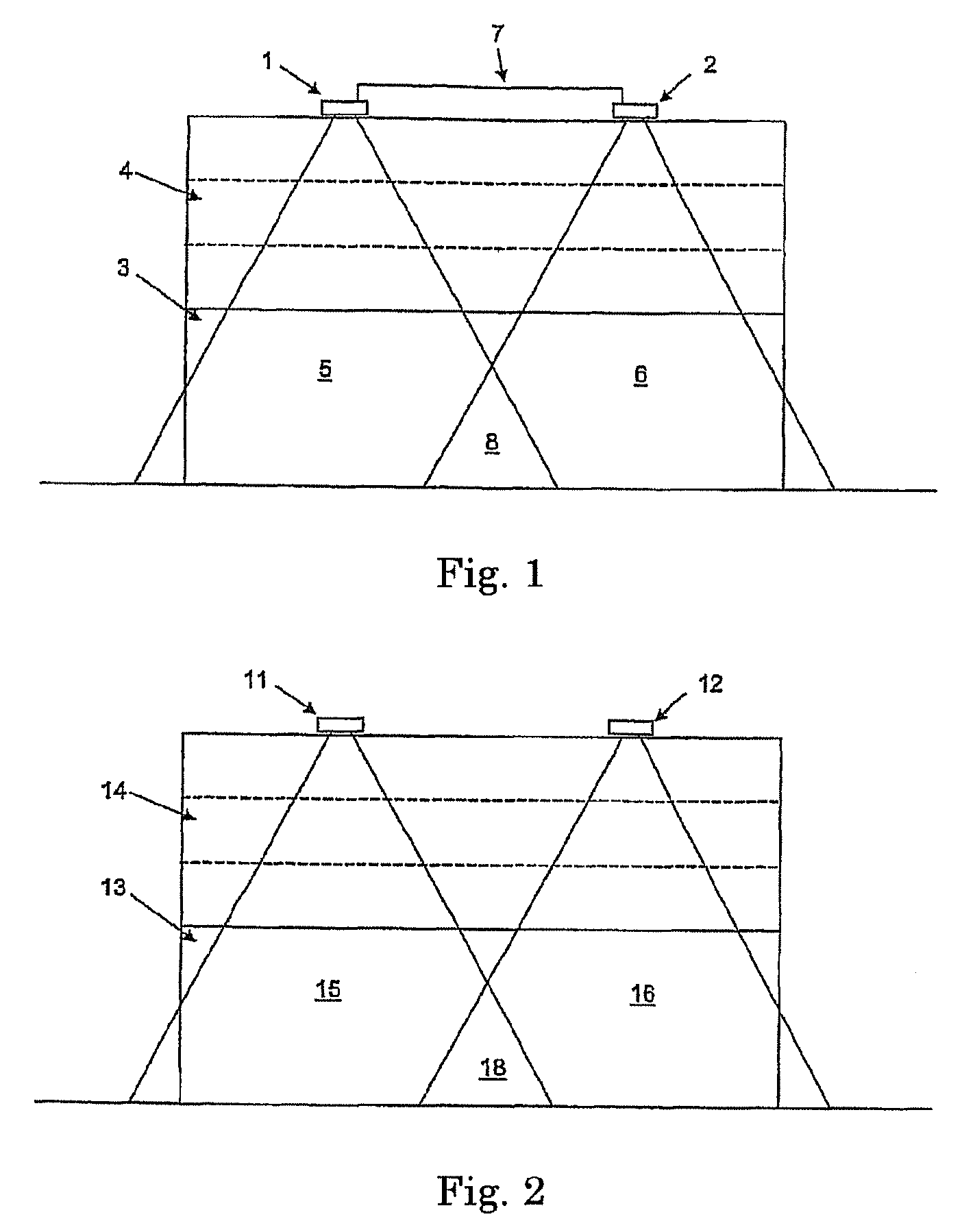
[0040]FIG. 1 illustrates two sensor devices 1, 2. These sensor devices 1, 2 monitor a roller door 4 for opening and closing an opening 3. The sensors 1, 2 have monitoring areas 5, 6. The monitoring areas 5, 6 overlap in a central area 8. The overlapping area 8 may result in defective measurements which make it impossible for the sensor devices 1, 2 to operate reliably.

[0041]The sensor devices 1, 2 are electrically connected to one another by means of a connection 7. Internally, the connection connects an input or an output of each sensor (not illustrated). If the sensor device 1 would like to carry out a measurement, a check is carried out in order to determine whether a signal from the output of the sensor device 2, which indicates a current measuring operation of the sensor device 2, is applied to the input 1 of the sensor device 1. If this is the case, the sensor device 1 is preferably designed in such a manner that it enters a waiting position for a predefined, optionally random...


PUM


Abstract

The invention proposes a sensor array having a plurality of sensor devices comprising a source of electromagnetic radiation, a receiver for the electromagnetic radiation and a control device, the control device being designed to use the source to emit electromagnetic radiation and being designed to determine a distance covered by electromagnetic radiation, which is emitted by the source, from a reflection surface of an object to the receiver by evaluating the reflected radiation. According to the invention, the sensor devices of the plurality of sensor devices operate at different frequencies or using time-division multiplexing. The invention also proposes a sensor device for a sensor array, the control device being designed to measure the distance at different frequencies or using time-division multiplexing.

Description

CROSS REFERENCE TO RELATED APPLICATIONS[0001]This application is a continuation of International Application No. PCT / EP2006 / 011478, having an international filing date of Nov. 30, 2006, and claims the benefit under 35 USC §119(a)-(d) of German Application No. 10 2005 058 094.7, having a filing date of Dec. 5, 2005 and German Application No. 10 2006 050 303.1, having a filing date of Oct. 23, 2006, the entireties of which are incorporated herein by reference.FIELD OF THE INVENTION[0002]The invention relates to a sensor array and to a sensor device comprising a source, for example, electromagnetic radiation, in particular light, a receiver for the electromagnetic radiation and a control device.BACKGROUND OF THE INVENTION[0003]TOF sensors (Time of Flight sensors) emit light and use the reflected light to determine the distance covered by the light from a reflection surface back to the sensor. This can be achieved, for example, by measuring the time required by a light pulse to pass fro...

Claims


Application Information

Patent Timeline
Patent Type & Authority Patents(United States)
IPC IPC(8): G01B11/14G01S17/04G01S17/87
CPCG01S7/023G01S7/497G01S17/026G01S17/87G01V8/20G01S17/04
Inventor DE COI, BEAT
Owner CEDES AG
Why Eureka
Try Eureka