Self-cooled electro-magnetic audio transducer

a self-cooled, electro-magnetic technology, applied in the direction of electrical transducers, deaf-aid sets, transducer details, etc., can solve the problems of limited design, reduced voice coil temperature, and high design cos

Inactive Publication Date: 2010-11-09
EARTHQUAKE SOUND
View PDF7 Cites 43 Cited by
  • Summary
  • Abstract
  • Description
  • Claims
  • Application Information

AI Technical Summary

Benefits of technology

[0011]The present invention is an electro-magnetic audio transducer that is self-cooling by inhaling and exhausting an area that is separated from the reminder of the transducer by an instantaneous decrease or increase, respectively, of the pressure within that area by the movement of a coil when electrically excited. The coil being wound on a bobbin that defines an interior cavity that changes in size as the coil is excited causing that size

Problems solved by technology

However, some of those designs are very expensive and their cost makes them unmarketable, there are others that produce marginal cooling, and still others that offer virtually no cooling.
Unfortunately, these types of a cooling systems only provide cooling of the inside surface of the vertical passage of the pole piece with the temperature of the voice coil only reduced by the inefficient convection of heat transferred from the voice coil to the pole piece and by conduction from the outside of the pole piece to the inside of the voice coil.
This design is thus limited to the use of a special speaker basket, only mounting the speaker motor to the outside bottom of the basket, and the machining of the opposing venturi passages through the interior bottom portion of the pole piece.
Thus this design requires expensive machining of the pole piece and greatly limits variations on the design of the completed speakers that can utilize this cooling technique making it very impractical for all of those reasons

Method used


Image

  • Self-cooled electro-magnetic audio transducer
  • Self-cooled electro-magnetic audio transducer
  • Self-cooled electro-magnetic audio transducer

Examples


Embodiment Construction

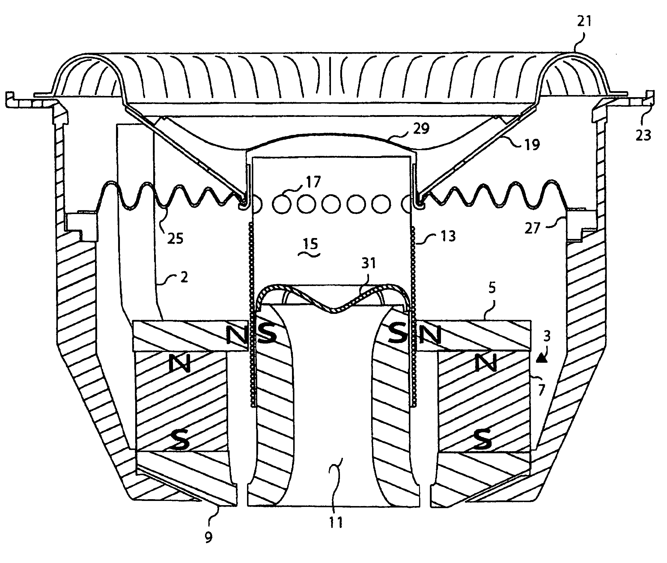
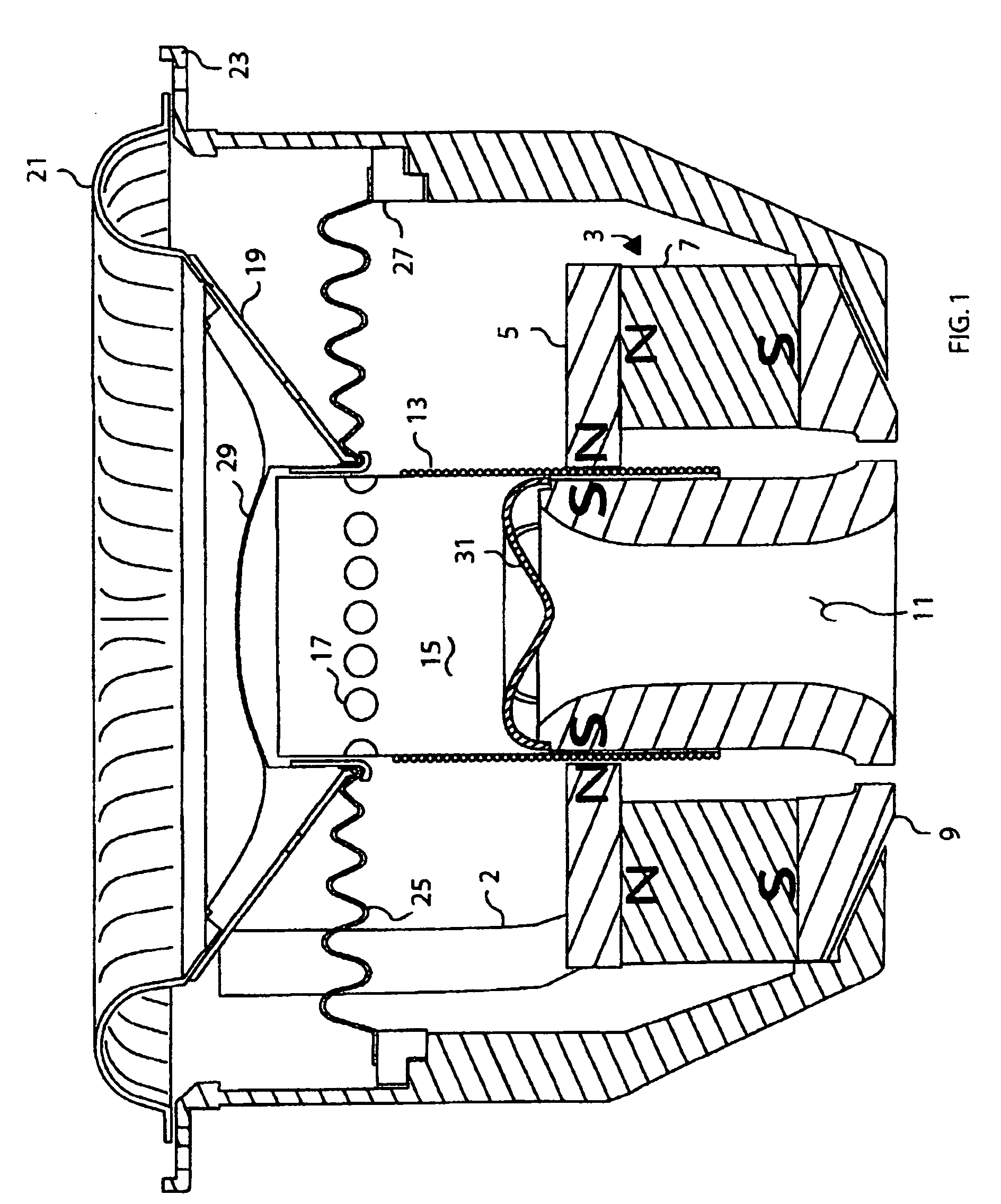
[0023]The following discussion is of an example embodiment of the self-cooling electro-magnetic audio transducer of the present invention as illustrated in the accompanying figures.

[0024]The example embodiment of the present invention discussed below pertains to a self-cooling audio speaker. Typically speakers have a motor structure that includes a magnet, back plate, pole piece, and a top plate. While the motor is stationary, a voice coil is always moving as a result of the changing electro-magnetic field created by the voice coil in interaction with the constant magnitude magnetic field of the magnet. As the voice coil moves it causes the cone, or diaphragm, attached to the voice coil to also move to create an acoustic wave from the surface thereof. This motion has also been used to provide cooling of the voice coil to minimize the probability of burn-out thereof. While many cooling designs have been disclosed in the past, they require costly modifications to various components in...


PUM


Abstract

An electro-magnetic audio transducer that is self-cooling by inhaling and exhausting an area that is separated from the reminder of the transducer by an instantaneous decrease or increase, respectively, of the pressure within that area by the movement of a coil when electrically excited. The coil being wound on a bobbin that defines an interior cavity that changes in size as the coil is excited causing that size to increase or decrease thus inhaling or exhausting, respectfully, air into or out of the cavity by the pressure change. That movement of air resulting in convective cooling of the coil and transducer. The bobbin encircling a magnetic pole piece with a cooling cap on top thereof with slots therethrough through which air is drawn in opposite directions as the size of the cavity within the bobbin changes size as the coil is electrically excited.

Description

BACKGROUND OF THE INVENTION[0001]1. Field of the Invention[0002]The present invention relates generally to electro-magnetic transducers and, more particularly, to electro-magnetic transducers that are self-cooled by means of instantaneous pressure changes created by the natural motion of the transducer coil and the bobbin on which it is wound.[0003]2. Description of the Prior Art[0004]There are many electro-magnetic transducers on the market that were designed for the purpose of self-cooling. However, some of those designs are very expensive and their cost makes them unmarketable, there are others that produce marginal cooling, and still others that offer virtually no cooling. Most common designs include a vertical venting passage through the center of the pole piece of the electro-magnetic motor of loudspeakers. The vertical passage, during an outward stroke of the voice coil of the electro-magnetic motor causes cold air to be sucked from beneath the electro-magnetic motor into the...

Claims


Application Information

Patent Timeline
IPC IPC(8): H04R25/00
CPCH04R9/022
Inventor SAHYOUN, JOSEPH Y.
Owner EARTHQUAKE SOUND
Why Eureka
Try Eureka