Vial-mounting structure

a technology of mounting structure and vial, applied in the field of level, can solve the problems of prone disassembly of the vial from the frame, disadvantages of certain devices of the prior art, glueing of the mounting structure, etc., and achieve the effect of convenient level assembly and accurate mounting of the vial

Active Publication Date: 2010-11-16
MILWAUKEE ELECTRIC TOOL CORP
View PDF24 Cites 20 Cited by
  • Summary
  • Abstract
  • Description
  • Claims
  • Application Information

AI Technical Summary

Benefits of technology

[0007]Another object of this invention is to provide a vial-mounting structure which provides secure holding of a vial within a topnotch.
[0009]Still another object of the invention is to provide a vial-mounting structure which facilitates accurate mounting of the vial with respect to the frame.
[0010]Another object of the invention is to provide a vial-mounting structure which facilitates easy assembly of a level.
[0020]The locking member preferably has a lower portion and two upward portions. The lower portion defines the threaded aperture. Each upward portion extends from the lower portion to terminate at an upper end which engages the frame inner surface. The vial-holding member preferably has two side portions extending from opposite sides of the bottom portion. Each side portion includes a vertical projection key. It is preferred that each of the upward portions of the locking member defines a keyway receiving a corresponding projection key therethrough. The key-keyway mating engagement facilitates alignment of the locking member and the vial-holding member.

Problems solved by technology

However, such positioning also presents a challenge for securing the vial to the frame.
Because of the open nature of the topnotch, the vial is prone to becoming disassembled from the frame upon various impacts caused by the occasional dropping of the level or other disruptive occurrences at a construction site.
Such arrangements, however, have problems and disadvantages rendering them problematic in many situations.
Certain devices of the prior art are disadvantageous in requiring glueing of the mounting structure to portion of the level body.
Some such prior arrangements are designed to secure the vial by extending forces directed away from each other to engage inner surfaces of opposite walls of the level frame, but such arrangements have disadvantages related to adaptability for varying level sizes and in some cases related to ease of assembly.
The problem of such construction is that the vial-holding part has to be accurately dimensioned for a particular level size such that this vial-holding part spans the distance between top and bottom walls to hold the vial at the correct position along the topwall.
Another example of such arrangements is described in JP 2007-24790 (Feb. 1, 2007), but such arrangement pose difficulties in assembly because of the to need to gain access to internal fasteners from the end of the level body.

Method used


Image

  • Vial-mounting structure
  • Vial-mounting structure
  • Vial-mounting structure

Examples


Embodiment Construction

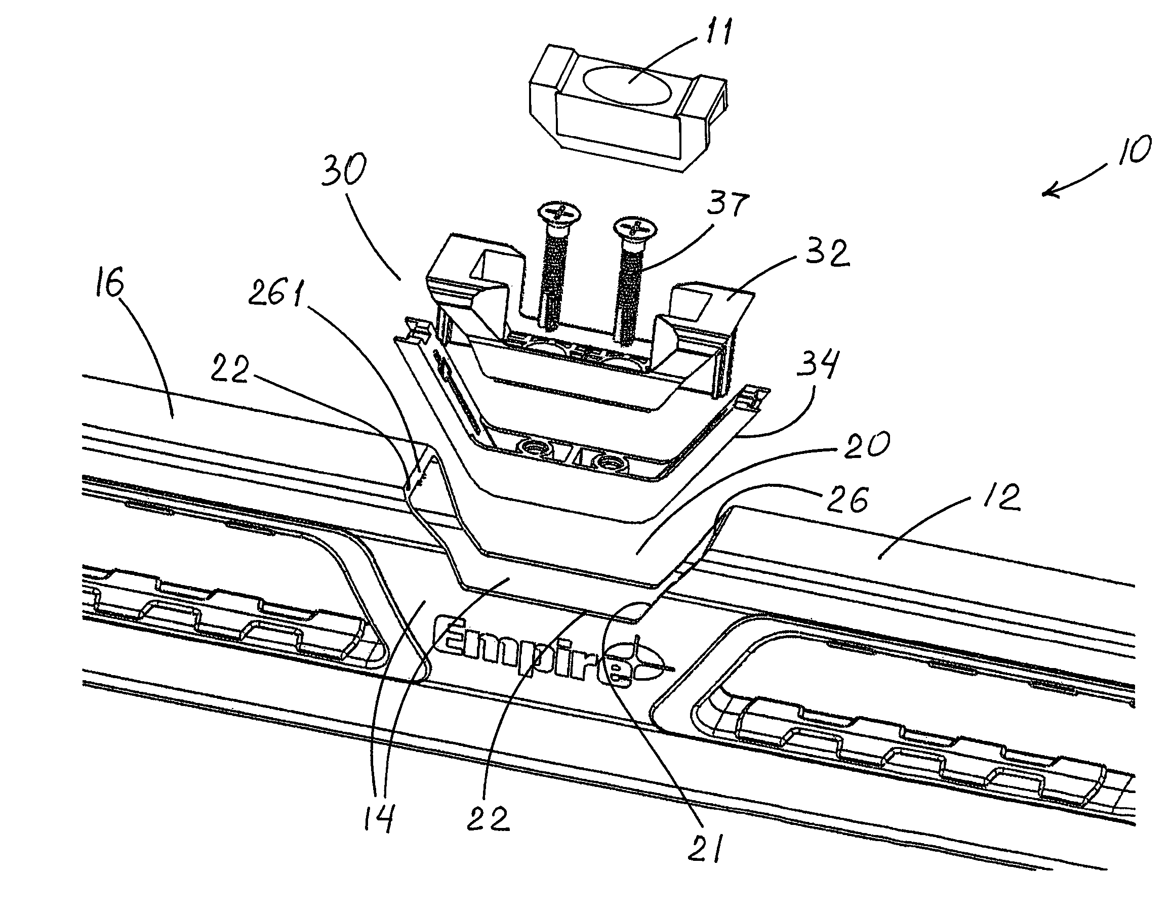
[0039]The drawings show a level 10 that includes an elongate hollow frame 12 with two sidewalls 14 and a topwall 16 extending therebetween. Walls 14 and 16 define a topnotch 20 and have notch-defining edges 21 which include non-vertical surfaces 22. A vial 11 is mounted within topnotch 20.

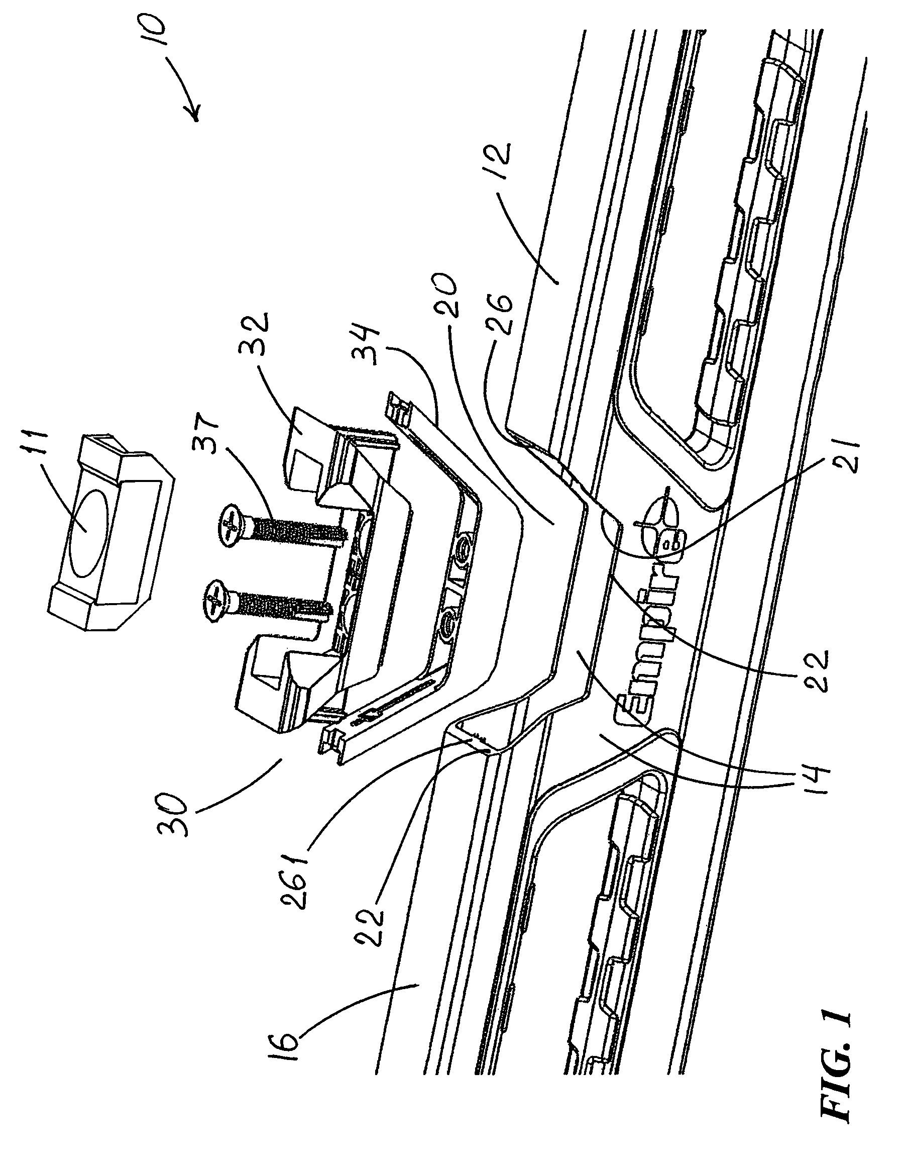
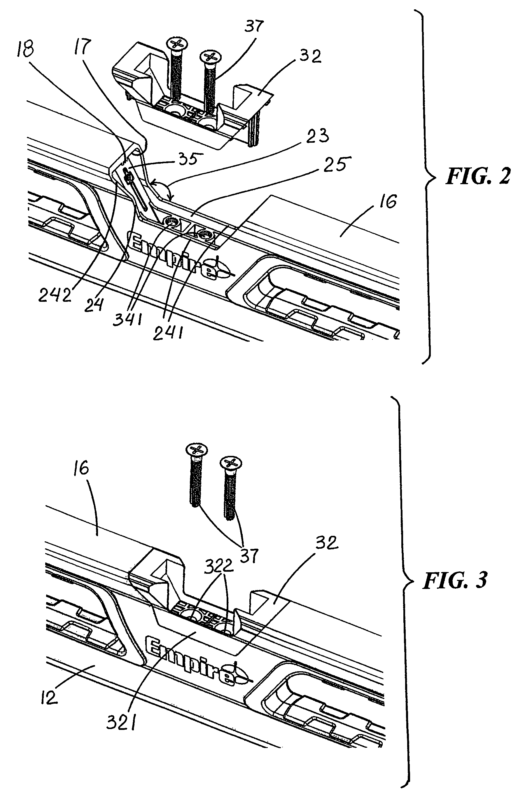
[0040]FIG. 1 shows that level 10 with an inventive vial-mounting structure 30 which includes a vial-holding member 32 and a locking member 34 movably secured with respect to vial-holding member 32. As best seen in FIGS. 3-7, vial-holding member 32 is configured for resting on non-vertical notch-edge surfaces 22. Locking member 34 includes frame-engaging portions 35 which press upwardly against a frame inner surface 13 (see FIGS. 2 and 7) to pull vial-holding member 32 downwardly against non-vertical notch-edge surfaces 22. As seen in FIGS. 4 and 6-8, such downward pulling secures vial-holding member 32 to frame. FIG. 7 further illustrates frame-engaging portions 35 of locking member 34 pressing upw...


PUM


Abstract

A level including an elongate hollow frame with two sidewalls and a topwall extending therebetween, a topnotch defined by the walls which have notch-defining edges including non-vertical surfaces, and a vial within the topnotch. A vial-mounting structure includes a vial-holding member and a locking member movably secured with respect to the vial-holding member. The vial-holding member is configured for resting on the non-vertical notch-edge surfaces. The locking member includes frame-engaging portions which press upwardly against a frame inner surface to pull the vial-holding member downwardly against the non-vertical notch-edge surfaces, thereby securing the vial-holding member to the frame. A method for securing a vial-mounting structure to the level by providing the vial-mounting structure, which includes the vial-holding member, and pulling the vial-holding member downwardly against the non-vertical notch-edge surfaces by a force from inside the frame, thereby securing the vial-holding member to the frame.

Description

FIELD OF THE INVENTION[0001]This invention relates to levels and, more particularly, to structures for accurately and reliably securing vials to levels.BACKGROUND OF THE INVENTION[0002]In the construction industry, levels are used to ensure that structural members are installed in their exact intended orientations. Levels include plural vials, almost always including a principal center vial which is parallel to a reference surface and used to indicate a horizontal orientation. Such horizontal vial is normally secured to the level frame in a position that permits viewing of the vial from both sides and also from above to ascertain the orientation of substantially horizontal surfaces. The most desirable positioning of such vial is within a topnotch in the body of a level which topnotch is defined by two sidewalls and the topwall of a hollow level body frame. However, such positioning also presents a challenge for securing the vial to the frame. Because of the open nature of the topnot...

Claims


Application Information

Patent Timeline
Patent Type & Authority Patents(United States)
IPC IPC(8): G01C9/28
CPCG01C9/28
Inventor CHRISTIANSON, JOHN
Owner MILWAUKEE ELECTRIC TOOL CORP
Why Eureka
Try Eureka