Opposite radial rotary-piston engine of Choronski

a rotary-piston engine and choronski technology, applied in the direction of sliding valves, valve arrangements, mechanical equipment, etc., can solve the problems of limited operation resource for its loaded parts, large friction loss of the unit, and inability to rotate the system including movable parts, etc., to achieve the effect of enhancing the efficiency, size and weight of the engin

Inactive Publication Date: 2010-11-16
CHORONSKI EVGENI +1
View PDF5 Cites 4 Cited by
  • Summary
  • Abstract
  • Description
  • Claims
  • Application Information

AI Technical Summary

Benefits of technology

[0012]To overcome the mentioned drawbacks of the engine in U.S. Pat. No. 7,584,726, an inventive two-stroke opposite radial rotary-piston engine is proposed herein. It comprises a cylinder block including sleeves, pairs of pistons slidely disposed within the sleeves and oppositely movable, each piston has a rod. The engine comprises guiding bearings, a power takeoff shaft, two rotors mounted on the shaft, each having an inner surface formed by a closed curved line, the rotors' transverse axes are disposed mutually perpendicularly. On the frontal part, the rotors have concaved surface portions made along the curved line. The engine comprises T-like traverses, pair-wise spanning the rods of the pistons. Each traverse includes a convex spherical protrusion, cooperating with the concaved portion during a start of the engine. A clearance between the concaved and convex portions is provided after the start. The engine comprises support bearings, each coupled to one of the traverses. Support bearings each includes an external bushing, capable of rolling over the inner surface of the rotor associated with the traverse, thereby impelling the rotor. Other elements (orifices, etc.) are added, enhancing the efficiency, size, and weight of the engine. Alternative module engine embodiments are also described, providing power variety of the engines.

Problems solved by technology

DE3907307 discloses a four-stroke engine wherein a cylinder block revolves inside a rotor, which is complicated, has a small resource of the valve system, and an imbalance with the revolving system including movable parts.
It is a complicated unit with substantial friction losses, which has a limited operation resource for its loaded parts.
The construction does not eliminate the side forces exerted by the piston upon the cylinder walls.
The construction is complicated and difficult to balance (which is admitted by its author).
The place of contact with the housing experiences high friction and heating, and thus will have a short operation resource.
That engine however has also certain drawbacks and limitations.
Reaction forces produced in support bearings are very significant that leads to a short operation resource period.
This necessitates the use of complicated sealing means that, as a rule, have very limited operation resource (typically 100 hours maximum).
The rotating cylinder block with linearly reciprocating pistons is very hard to balance, and thusly will cause intensive destructive vibrations.
Hence, their replacement would require dissembling the entire engine, which makes maintenance of the engine taught in U.S. Pat. No. 4,334,506 more difficult.
However, the design of engine taught in U.S. Pat. No. 7,584,726 has certain drawbacks: the rotor has a significant size and weight, the support roll bearings don't allow absorbing high loads, which shortens the service lifespan thereof.
The power takeoff is carried out upon each 180-degree turn, i.e. the load characteristic is uneven that also reduces the lifespan and efficiency of that engine.

Method used


Image

  • Opposite radial rotary-piston engine of Choronski
  • Opposite radial rotary-piston engine of Choronski
  • Opposite radial rotary-piston engine of Choronski

Examples


Embodiment Construction

[0025]While the invention may be susceptible to embodiment in different forms, there are shown in the drawings, and will be described in detail herein, specific embodiments of the present invention, with the understanding that the present disclosure is to be considered an exemplification of the principles of the invention, and is not intended to limit the invention to that as illustrated and described herein.

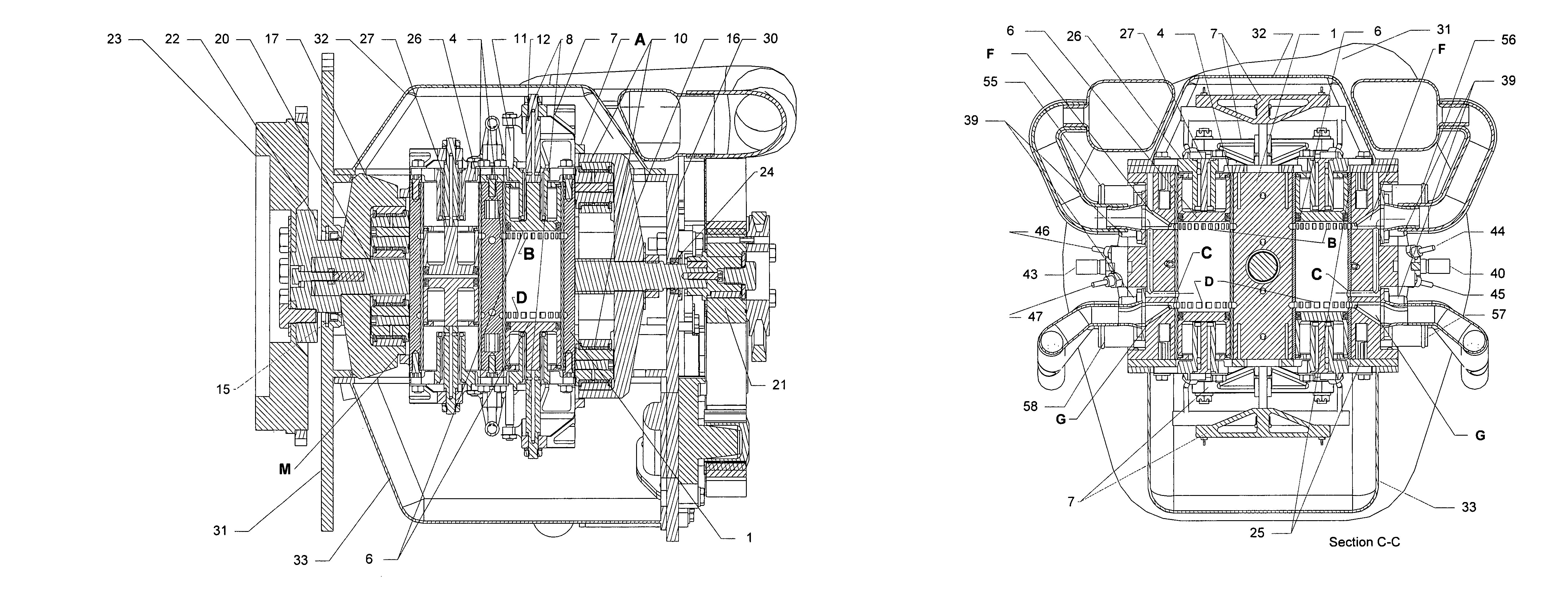
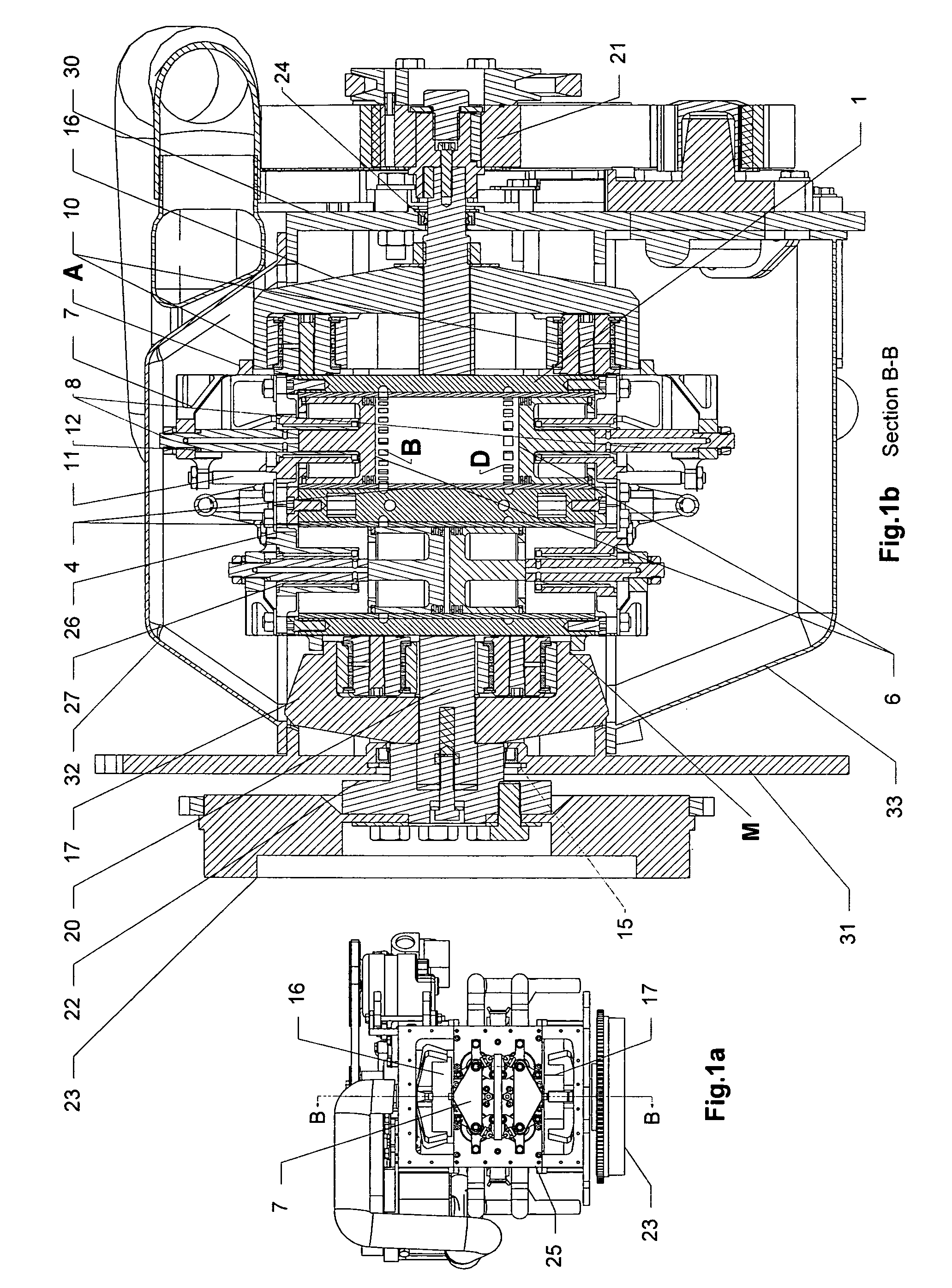
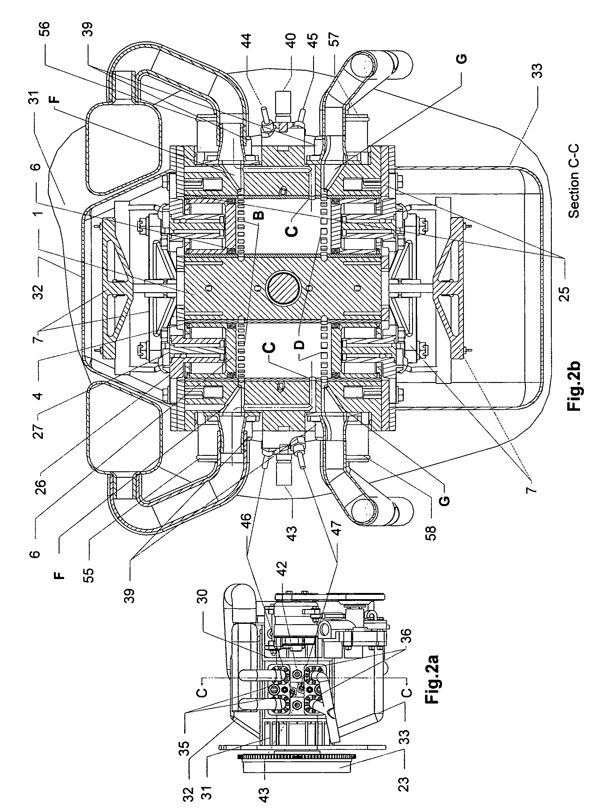
[0026]A preferred embodiment of the inventive engine is illustrated on FIGS. 1a, 1b, 2a, 2b, 3a, 3b, and 4. It is a two-stroke internal combustion engine featuring oppositely disposed pistons movable toward each other, which movement is essentially converted into the spinning of the rotors, also featuring the straight blowing of air through cylinders with the straight injection of fuel, and with liquid cooling.

[0027]The engine comprises a hollow stationary cylinder block (1) fixedly mounted, e.g. on a vehicle; a frontal housing (30) and a rear housing (31) fixedly mounted, e.g. ...


PUM


Abstract

A two-stroke opposite radial rotary-piston engine is proposed, comprising a block including sleeves, pairs of pistons disposed within the sleeves and oppositely movable, guiding bearings, a power takeoff shaft, rotors mounted thereon having an inner surface formed by a closed curved line, the rotors' transverse axes are predeterminedly disposed. On the frontal part, the rotors have concaved surface portions along the curved line. T-like traverses are mounted, pair-wise spanning the pistons. The traverses include convex protrusions, cooperating with the concaved portions during the start of the engine. A clearance between the concaved and convex portions is provided after the start. The engine comprises support bearings, coupled to traverses. Support bearings include an external bushing, rolling over the inner surface of the rotor associated with the traverse, thereby impelling the rotor. Other elements and alternative module embodiments are added, enhancing the efficiency, size, weight, and power variety of the engine.

Description

FIELD OF THE INVENTION[0001]The invention relates to opposite radial rotary-piston engines that can be utilized in ground vehicles, water vehicles, aircraft, in combinations with generators, etc.BACKGROUND OF THE INVENTION[0002]In the prior art there are known several constructions of centrifugal-piston or rotary-piston engines (herein further called ORPE), which are intended to eliminate certain disadvantages of conventional piston engines. E.g., such constructions are described in DE3907307, U.S. Pat. No. 6,279,518, U.S. Pat. No. 4,334,506, WO2005098202, RU2143572, and JP7113452. The latter, for instance, has the purpose “to suppress the side pressure applied to a piston, improve efficiency, reduce vibration and drastically reduce dimension and weight, by revolving a cam on the inner wall of an ellipse without using a crank, in reciprocating motion.” The other above indicated constructions typically have similar purposes.[0003]DE3907307 discloses a four-stroke engine wherein a cyl...

Claims


Application Information

Patent Timeline
Patent Type & Authority Patents(United States)
IPC IPC(8): F02B25/00F02B33/08F02B75/28F02B33/14F02B75/30
CPCF02B53/14F02B63/04Y02T10/17Y02T10/12
Inventor CHORONSKI, EVGENIMOUKHAEV, BORIS
Owner CHORONSKI EVGENI
Why Eureka
Try Eureka