Marine fuel system with an ullage control device

a fuel system and control device technology, applied in the field of marine fuel systems, can solve problems such as excessive fuel consumption

Active Publication Date: 2010-11-16
BRUNSWICK CORPORATION
View PDF29 Cites 13 Cited by
  • Summary
  • Abstract
  • Description
  • Claims
  • Application Information

AI Technical Summary

Benefits of technology

[0036]In a particularly preferred embodiment of the present invention, the fuel system is configured to inhibit fuel from flowing into the first inlet after it has flowed into the quantity of fuel within the reservoir an...

Problems solved by technology

The system pumps an excessive amount of fuel through a plumbed fuel supply loop ...

Method used


Image

  • Marine fuel system with an ullage control device
  • Marine fuel system with an ullage control device
  • Marine fuel system with an ullage control device

Examples


Embodiment Construction

[0043]Throughout the description of the preferred embodiment of the present invention, like components will be identified by like reference numerals.

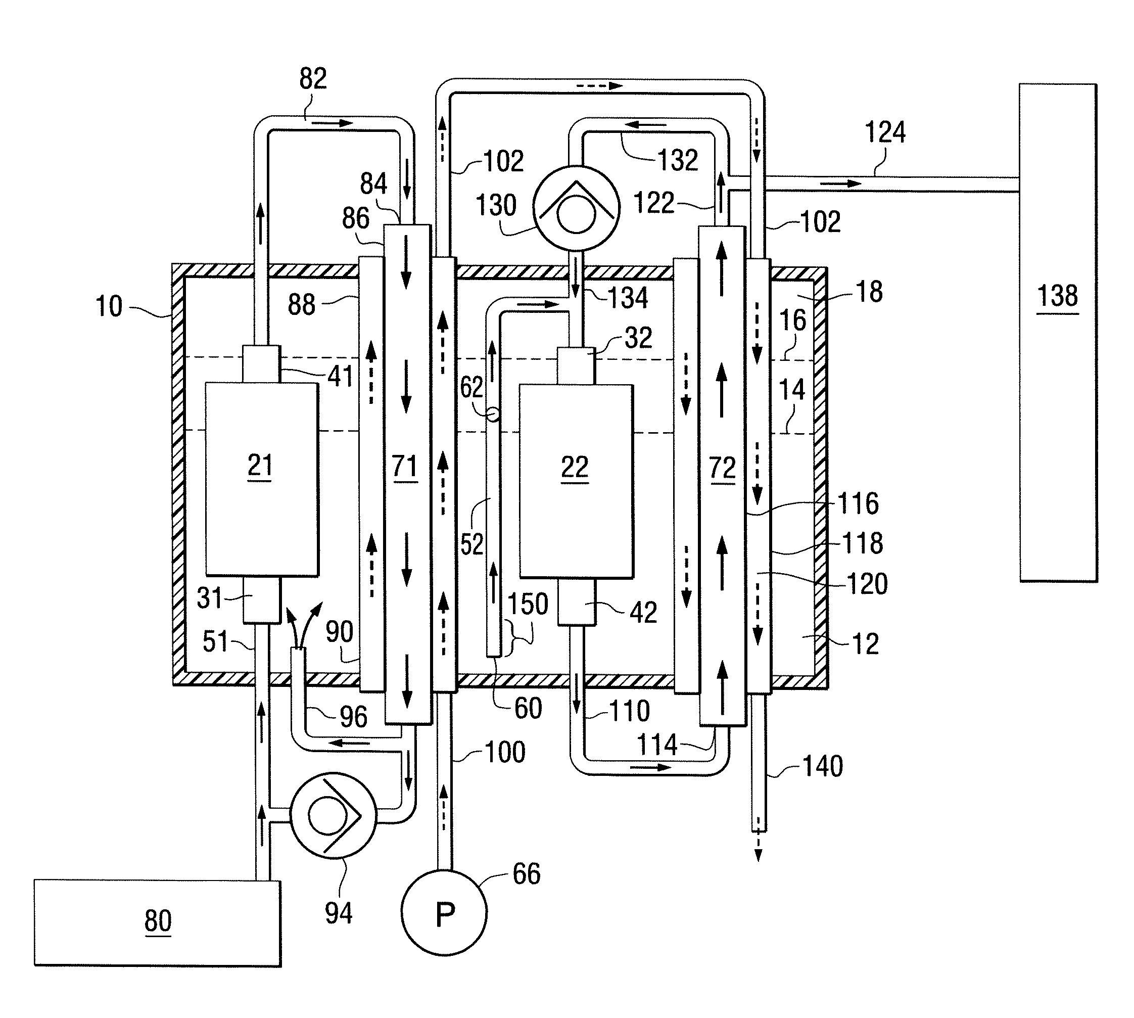
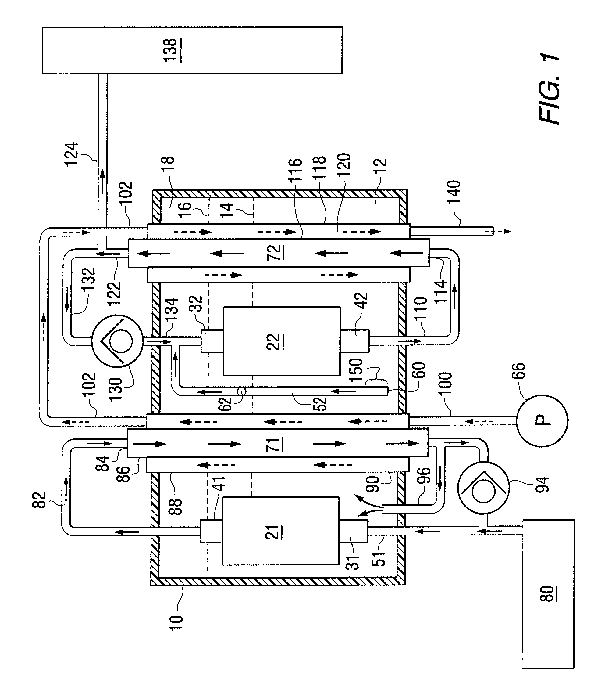
[0044]FIG. 1 is a schematic representation of a fuel system for a marine engine made in accordance with a preferred embodiment of the present invention. It is intended to illustrate several of the advantageous concepts embodied in applications of the present invention. The fuel system comprises a reservoir 10 which is configured to contain a quantity of fuel 12. As will be described in greater detail below, two dashed lines, 14 and 16, are used to represent two different hypothetical fuel levels which separate the liquid fuel from the ullage 18 above the liquid fuel. A preferred embodiment of the present invention further comprises a first fuel pump 21 having a first inlet 31 and a first outlet 41. A first inlet conduit 51 is connected in fluid communication with the first inlet 31. A preferred embodiment of the present invention furthe...


PUM


Abstract

A marine engine fuel system provides a low pressure lift pump to draw fuel from a fuel tank and cause the fuel to flow into a reservoir and a high pressure fuel pump which draws fuel from the reservoir and provides it to a fuel rail. An inlet conduit of the high pressure fuel pump is provided with a primary and a secondary opening. The secondary opening can be an orifice formed through a wall of the inlet conduit. The secondary opening is positioned, relative to the primary opening, at a location which assists in controlling the fuel level within the reservoir and the quantity of gaseous fuel contained within an ullage above the liquid pool of fuel.

Description

BACKGROUND OF THE INVENTION[0001]1. Field of the Invention[0002]The present invention is generally related to a marine fuel system and, more particularly, to a fuel system that provides primary and secondary openings in a fuel conduit to allow fuel vapor to be removed from the cavity of a fuel reservoir.[0003]2. Description of the Related Art[0004]Those skilled in the art of marine propulsion systems are aware of many different types of fuel systems. Some fuel systems use fuel vapor separators which are vented while others use unvented reservoirs. Some systems incorporate lift pumps and high pressure pumps within the structure of a fuel reservoir while others place these pumps outside the fuel reservoir. Certain marine propulsion systems use separate pumps to lift fuel from a fuel tank and to pressurize the fuel and induce it to flow to a fuel injection system. In all types of marine propulsion systems, it is beneficial to control the accumulation of fuel vapor within the system and...

Claims


Application Information

Patent Timeline
IPC IPC(8): F02M33/04F02M33/02
CPCF02M37/0052F02M37/103F02M37/14F02M37/18F02M33/08F02M37/0082
Inventor ABOU ZEID, AMIRREID, TIMOTHY S.KOLLMANN, TROY J.TORGERUD, MICHAEL A.MERTEN, BRIAN L.
Owner BRUNSWICK CORPORATION
Why Eureka
Try Eureka