
Saddle tee

a saddle tee and saddle technology, applied in the field of saddle tees, can solve the problems of time-consuming and tiring driving the piercing mechanism into the main line, affecting and reducing the service life of the main unit, so as to facilitate the installation of the base unit and strengthen the tap

Active Publication Date: 2010-11-16
HUSQVARNA AB
View PDF62 Cites 9 Cited by
  • Summary
  • Abstract
  • Description
  • Claims
  • Application Information

AI Technical Summary

Benefits of technology

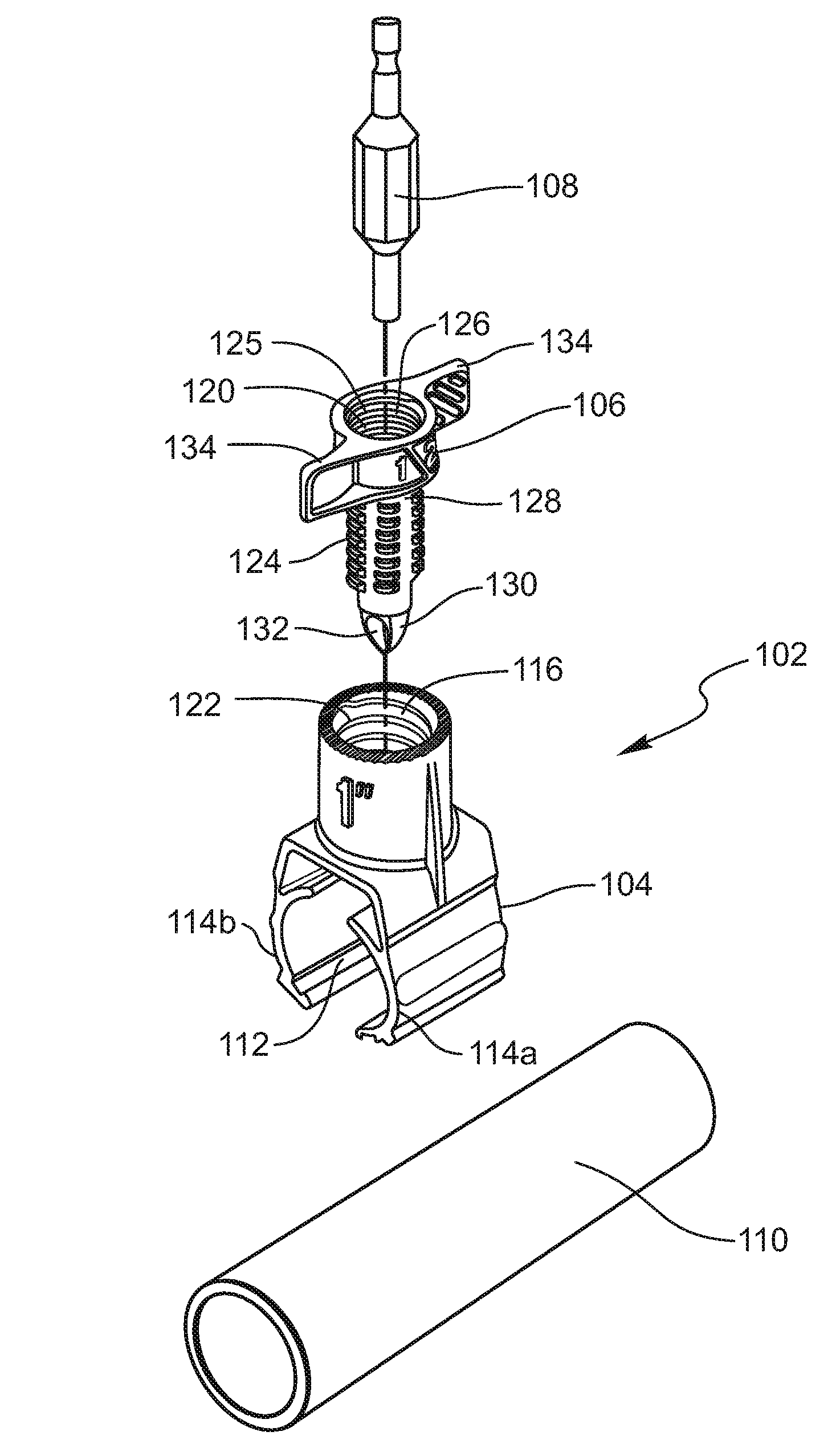
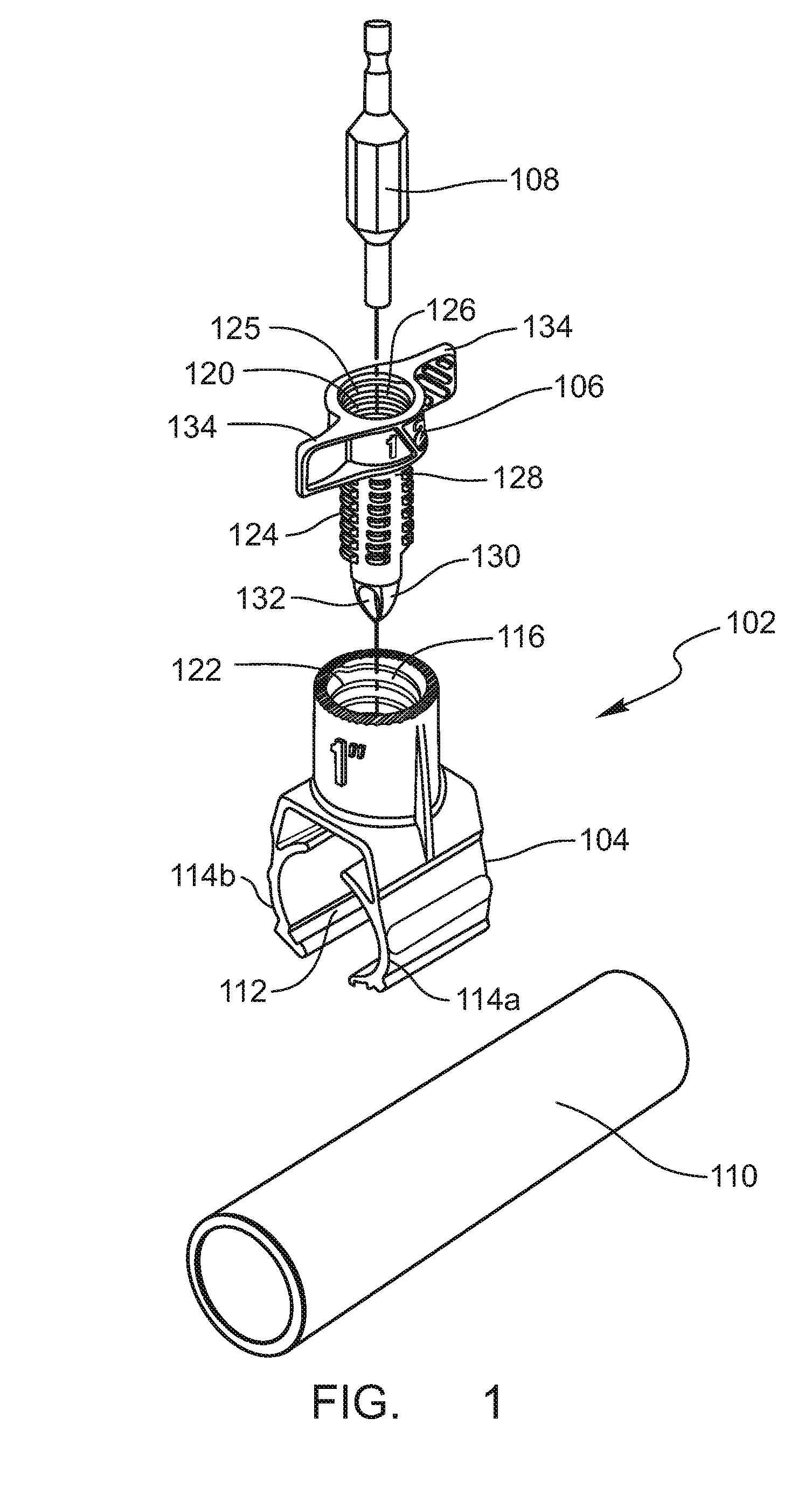
[0005]The tap defines a passageway and includes a tapered end. The tapered end includes an aperture in fluid communication with the passageway. The tap may also include a shaped portion for receiving a tool interface. The tool interface also interfaces with a power tool, such as a drill or an impact driver. Rotation of the power tool is translated through the tool interface to the tap, enabling the tap to be rapidly driven into the main line.
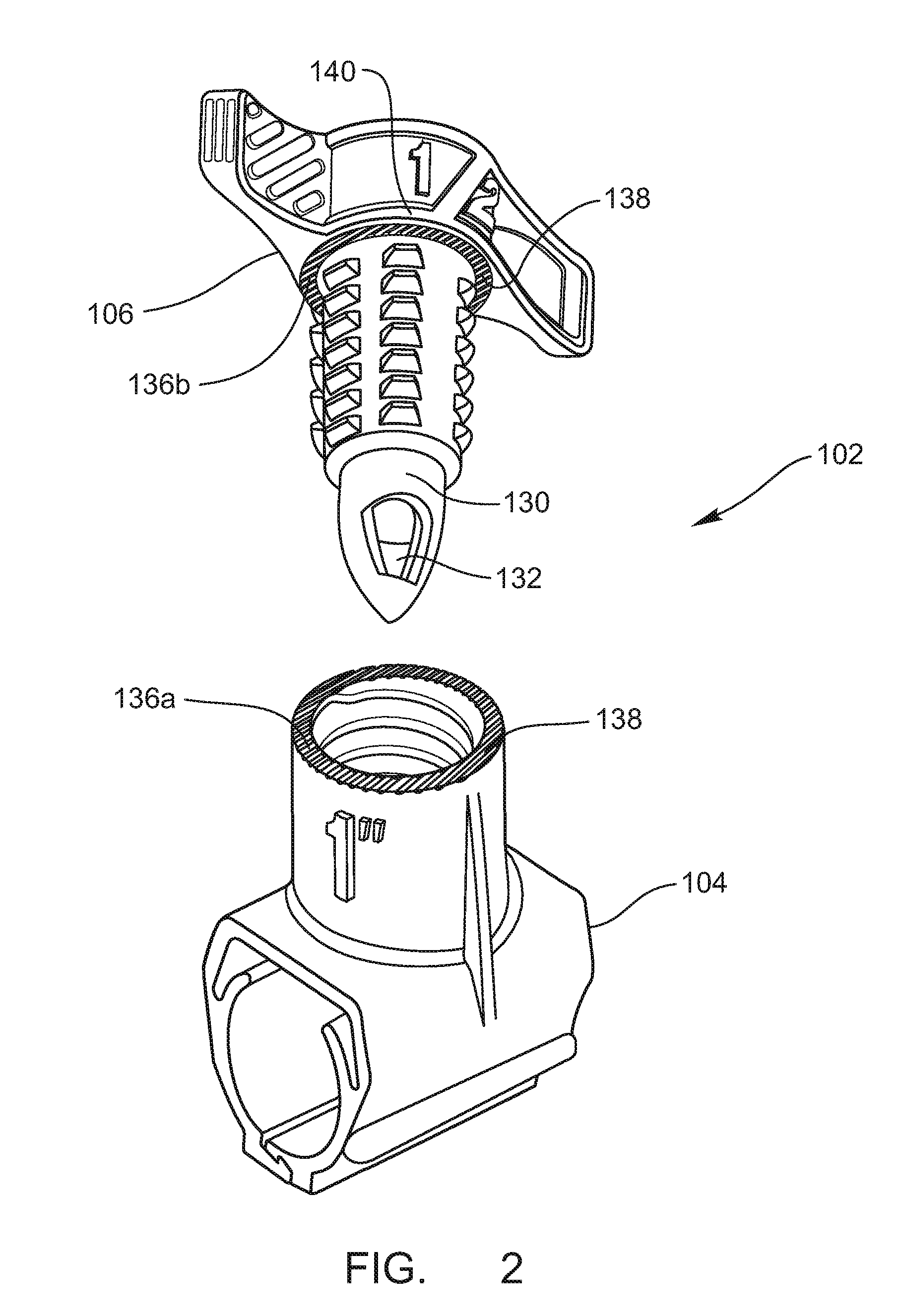
[0007]One embodiment of the disclosed saddle tee includes mating interface surfaces. A first interface surface on the base unit has a series of linearly aligned ridges. A second interface surface on a shoulder of a tap mates with the first interface to limit rotation of the tap relative to the base unit when the tap is fully inserted into the base unit. When the first interface is aligned and seated on the second interface, a threshold level of torque is required to rotate the tap relative to the base unit. The threshold level of torque, in one embodiment, is in excess of that which is likely to be reached without human intervention. In one embodiment, when the second interface surface is aligned and seated on the first interface surface, opposing apertures in the tapered of the tap are aligned to flow within the main line to facilitate fluid flow through the tap.
[0010]This sequence of events, resulting from the offset position of the first and second contact surfaces facilitates securing the arcuate interlocking jaws around the main line because the first interlocking end will position about on the main line first followed by the second interlocking end. The sequential positioning of the interlocking ends enables the interlocking ends to properly mate, securing the arcuate interlocking jaws around the main line without the need to manually adjust or interlock the interlocking ends. If the second interlocking jaw positioned about the main line first, the interlocking ends will not properly mate, requiring the user to manually align or interlock the interlocking ends. Thus, the design of the offset contact surfaces significantly facilitates installation of the base unit onto the main line.
[0011]In one embodiment, the tap includes a fitting with a gripping mechanism that grasps an end of a conduit with a smooth outer surface—without annular grooves, annular flanges, or annular beads—to secure the conduit within the fitting. Further, the tap and base unit may include raised text indicating the size of pipe with which the tap or base unit is capable of interfacing. With respect to the tap, the raised text may further comprise a reinforcing rib to strengthen the tap.

Problems solved by technology

Unfortunately, conventional saddle tees suffer from a number of disadvantages.
For example, driving the piercing mechanism into the main line can be time consuming and tiring.
Further, securing the main unit around the main line can be time consuming and often requires a user to clear a significant amount of space around the main line in order to properly access the main line.
Also, when fluid pressure enters the piercing mechanism, the piercing mechanism can become loose, potentially creating leaks or even dislodging the piercing mechanism from the main line.

Method used


Image

  • Saddle tee
  • Saddle tee
  • Saddle tee

Examples


Embodiment Construction

[0022]The presently preferred embodiments of the invention will be best understood by reference to the drawings, wherein like parts are designated by like numerals throughout. It will be readily understood that the components of the present invention, as generally described and illustrated in the figures herein, could be arranged and designed in a wide variety of different configurations. Thus, the following more detailed description of the embodiments of the present invention, as represented in FIGS. 1 through 8, is not intended to limit the scope of the invention, as claimed, but is merely representative of presently preferred embodiments of the invention.

[0023]As used herein, the term “in fluid communication with” means that fluid, if present, could pass from a first identified fluid passageway, object, opening, or aperture to a second fluid passageway, object, opening, or aperture. This term does not require that fluid be actually present within any of the identified fluid passa...


PUM

PropertyMeasurementUnit
sizeaaaaaaaaaa
torqueaaaaaaaaaa
timeaaaaaaaaaa

Abstract

An improved saddle tee for branching a conduit from a main line is disclosed. The saddle tee includes a base unit that defines an opening for receiving a tap and interlocking jaws for securing the base unit to a main line. The tap may include a shaped portion for receiving a tool interface to rotate the tap to drive the tap into the main line. The tool interface could be secured to a power tool to enable rapid driving of the saddle tee into the main line. The saddle tee may also include offset arcuate interlocking jaws to enable the jaws to interlock around the main line with ease. Optional interface surfaces on the tap and base unit enable the tap and base unit to interlock to limit rotation of the tap relative to the base unit when the tap is fully inserted into the base unit.

Description

BACKGROUND OF THE INVENTION[0001]A saddle tee is a device that is used to branch a conduit off of a main line. In other words, a saddle tee enables a secondary line to be connected to a main line. A conventional saddle tee includes a main unit that is placed around the main line and a piercing mechanism that is driven into the main line surrounded by the main unit.[0002]Unfortunately, conventional saddle tees suffer from a number of disadvantages. For example, driving the piercing mechanism into the main line can be time consuming and tiring. Further, securing the main unit around the main line can be time consuming and often requires a user to clear a significant amount of space around the main line in order to properly access the main line. Also, when fluid pressure enters the piercing mechanism, the piercing mechanism can become loose, potentially creating leaks or even dislodging the piercing mechanism from the main line.[0003]Accordingly, an improved saddle tee that resolves on...

Claims


Application Information

Patent Timeline
Patent Type & Authority Patents(United States)
IPC IPC(8): F16L41/04F16L41/14
CPCF16L41/06F16L47/345Y10T137/6123
Inventor HOSKISSON, SCOTWANGSGAARD, TRESENCE, ALAN T.
Owner HUSQVARNA AB
Learn More