Method for single side welding of laminate steel

a single-side welding and laminate steel technology, applied in the direction of welding apparatus, cutting tools, manufacturing tools, etc., can solve the problems of difficult access to the vehicle structure, difficult welding of electric resistance spots, and damage to the transmission of noise and vibration through the panel

Inactive Publication Date: 2010-11-16
GM GLOBAL TECH OPERATIONS LLC
View PDF8 Cites 8 Cited by
  • Summary
  • Abstract
  • Description
  • Claims
  • Application Information

AI Technical Summary

Problems solved by technology

The polymer has viscoelastic properties that dampen the transmission of noise and vibration through the panel.
However, in the collision repair environment it is often difficult to access the vehicle structure with squeeze type resistance spot welding equipment.
In addition, the electric resistance spot welding is made difficult by the fact that the polymer material is a dielectric and will not conduct electricity.
However the polymer layer tends to melt and mix with the weld.

Method used


Image

  • Method for single side welding of laminate steel
  • Method for single side welding of laminate steel
  • Method for single side welding of laminate steel

Examples


Embodiment Construction

[0016]The following description of certain exemplary embodiments is merely exemplary in nature and is not intended to limit the invention, its application, or uses.

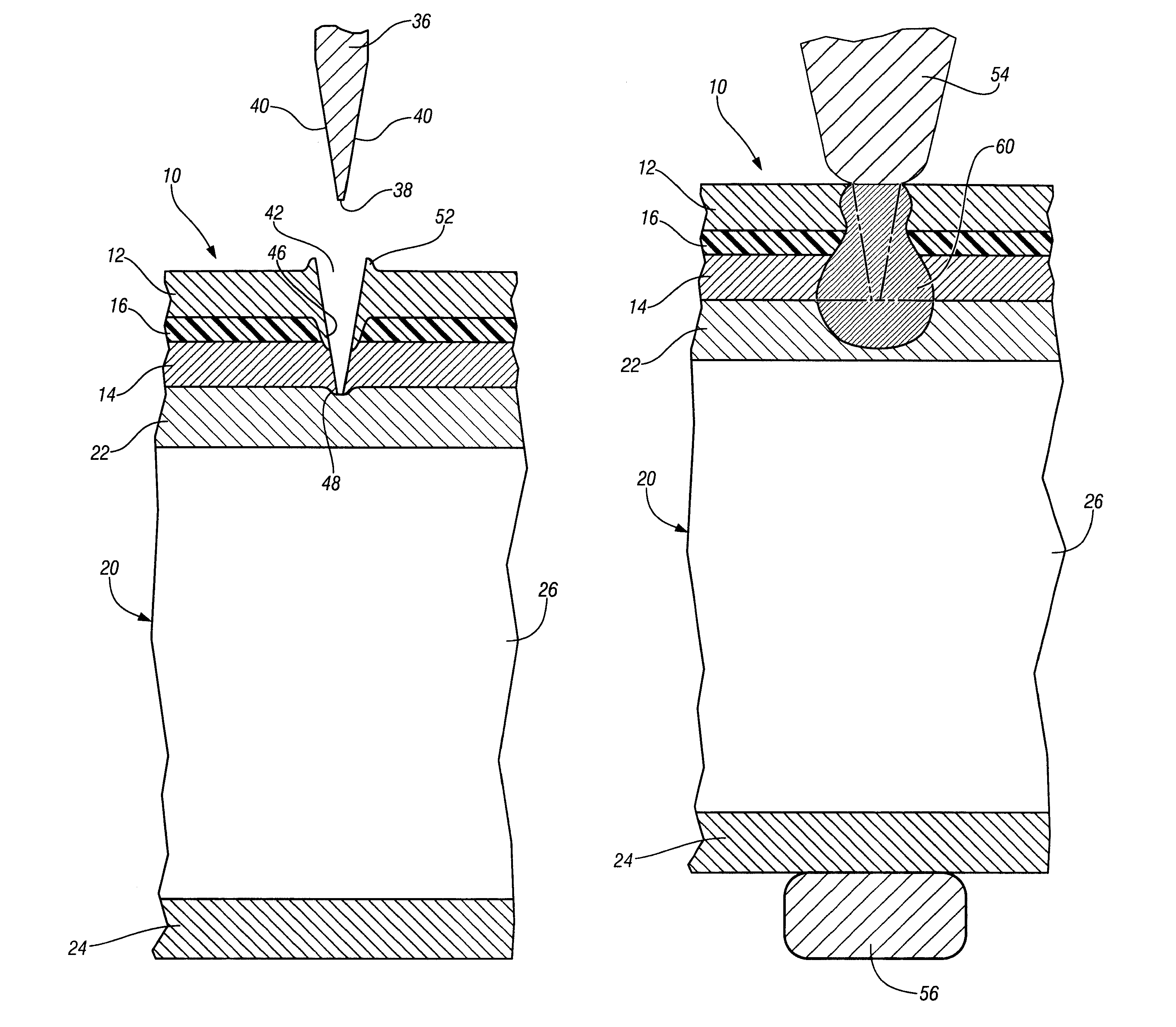
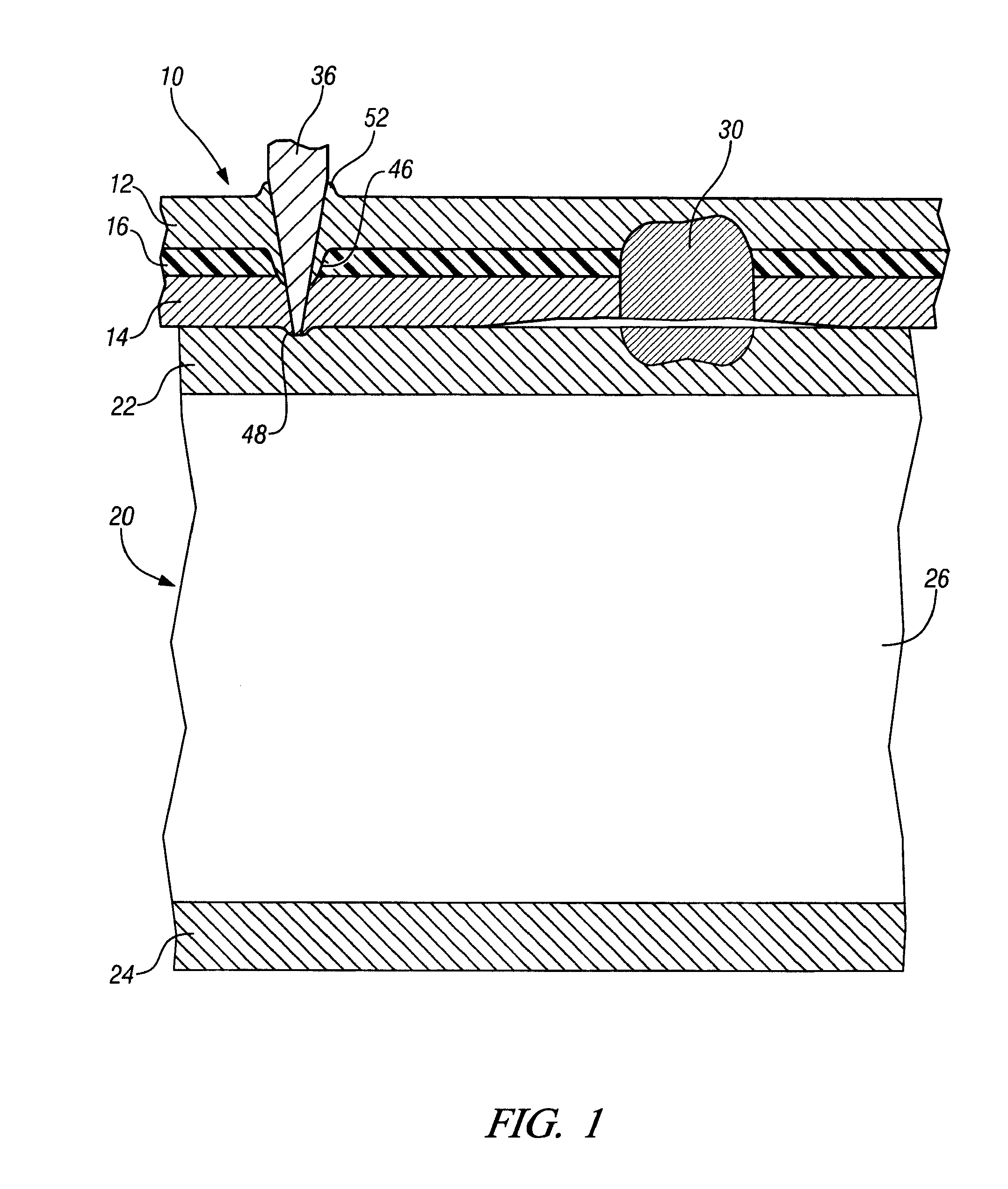
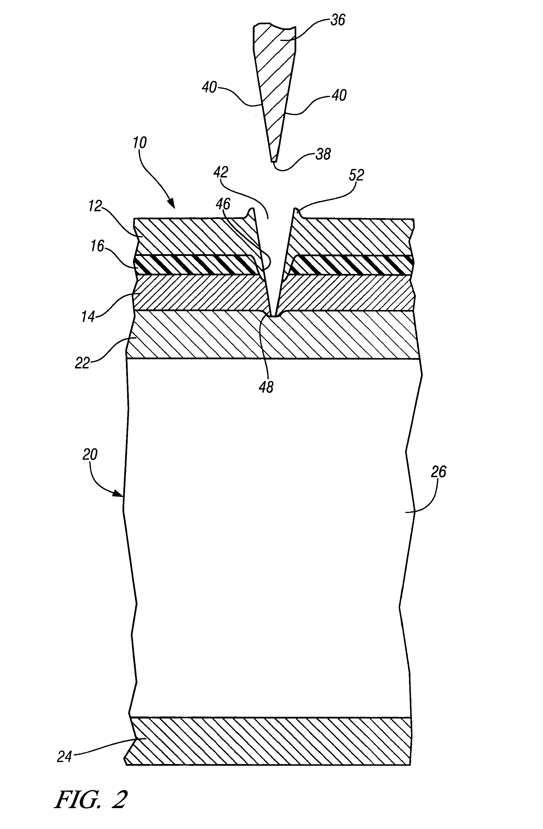
[0017]Referring to FIG. 1, a laminated steel panel 10 includes an upper steel sheet 12 and a lower steel sheet 14 with a layer of polymer material 16 interposed there between and bonding the steel sheets together. The total thickness of laminated steel can typically range between 0.8 mm to 3.0 mm. The polymer material is in the range of 0.025 mm-0.12 mm, but is shown as thicker in the drawing for sake of clarity.

[0018]A steel tube 20 includes a top wall 22, a bottom wall 24, a back side wall 26, and a front side wall, not shown. As shown in FIG. 1, cracked spot weld 30 is no longer able to attach the laminated steel panel 10 to the steel tube 20. Accordingly a new weld is needed to replace the cracked spot weld 30 and thereby repair the attachment of the laminated steel panel 10 to the steel tube 20.

[0019]FIG. 1 shows a p...


PUM

PropertyMeasurementUnit
total thicknessaaaaaaaaaa
electricaaaaaaaaaa
electric resistanceaaaaaaaaaa

Abstract

A method is provided for welding a laminated metal sheet to a workpiece. The laminated metal sheet includes an outer metal sheet and an inner metal sheet bonded together by a polymer material that impedes the flow of weld current. A punch is applied against the outer metal sheet and driven through the laminated metal sheet to create a hole and also create an annular metallic burr that bridges across the polymer material layer between the outer metal sheet and the inner metal sheet. A weld electrode is positioned against the outer metal sheet at the punched hole and weld current is conducted through the first annular metallic burr to create an electric resistance weld between the laminated metal and the workpiece.

Description

FIELD OF THE INVENTION[0001]The present invention relates to a method for creating a single side electric resistance spot weld between a sheet of laminated metal and a workpiece.BACKGROUND OF THE INVENTION[0002]It is known in modern automobile manufacture to use a laminated steel panel that is formed to shape in a conventional metal stamping press. Laminated steel is manufactured by bonding together a first steel sheet and a second steel sheet by a layer of polymer material that is cured in place between the first and second metal sheets to thereby attach the sheets together. The polymer has viscoelastic properties that dampen the transmission of noise and vibration through the panel.[0003]In the factory, the laminated steel panels can be successfully attached to vehicle structures such as tubular members by squeeze-type resistance spot welding. The factory environment of mass production enables process and quality control procedures that facilitate making of the welds.[0004]However...

Claims


Application Information

Patent Timeline
Patent Type & Authority Patents(United States)
IPC IPC(8): B23K11/00
CPCB23K11/002B23K11/11B23K11/163B23K11/34B23K2203/16B23K2103/16Y10T83/0481
Inventor WANG, PEI-CHUNGGOLLEHUR, ROBERT J.
Owner GM GLOBAL TECH OPERATIONS LLC
Why Eureka
Try Eureka