Supercharge Your Innovation With Domain-Expert AI Agents!

Radar apparatus

a technology of a radar and a meter, which is applied in the direction of instruments, measurement devices, and reradiation, can solve the problems of inability to accurately perform measurement and correction, and difficulty in accurately performing correction, and achieves simple processing, higher accuracy, and simple configuration and processing.

Inactive Publication Date: 2010-11-16
MURATA MFG CO LTD
View PDF12 Cites 5 Cited by
  • Summary
  • Abstract
  • Description
  • Claims
  • Application Information

AI Technical Summary

Benefits of technology

[0011]Accordingly, an object of the present invention is to provide a radar apparatus in which a voltage correction amount can be calculated with simple processing and high accuracy.

Problems solved by technology

With the apparatus described in Patent Document 1, however, unless the distance measured at each of the division points is accurate, it is difficult to accurately perform the correction.
In addition, because the FFT process executed in the short zone on the time basis deteriorates frequency resolution, the measurement and the correction cannot be accurately performed.

Method used


Image

  • Radar apparatus
  • Radar apparatus
  • Radar apparatus

Examples


first embodiment

[0045]A radar apparatus according to the present invention will be described with reference to the drawings.

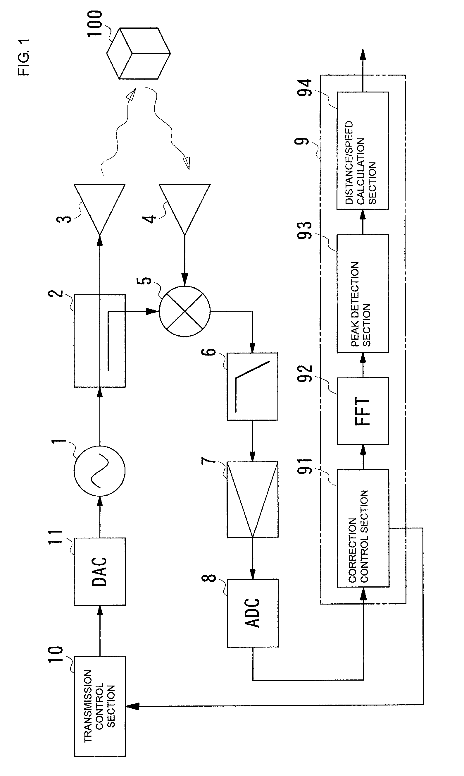
[0046]FIG. 1 is a block diagram illustrating a general configuration of the radar apparatus according to the first embodiment.

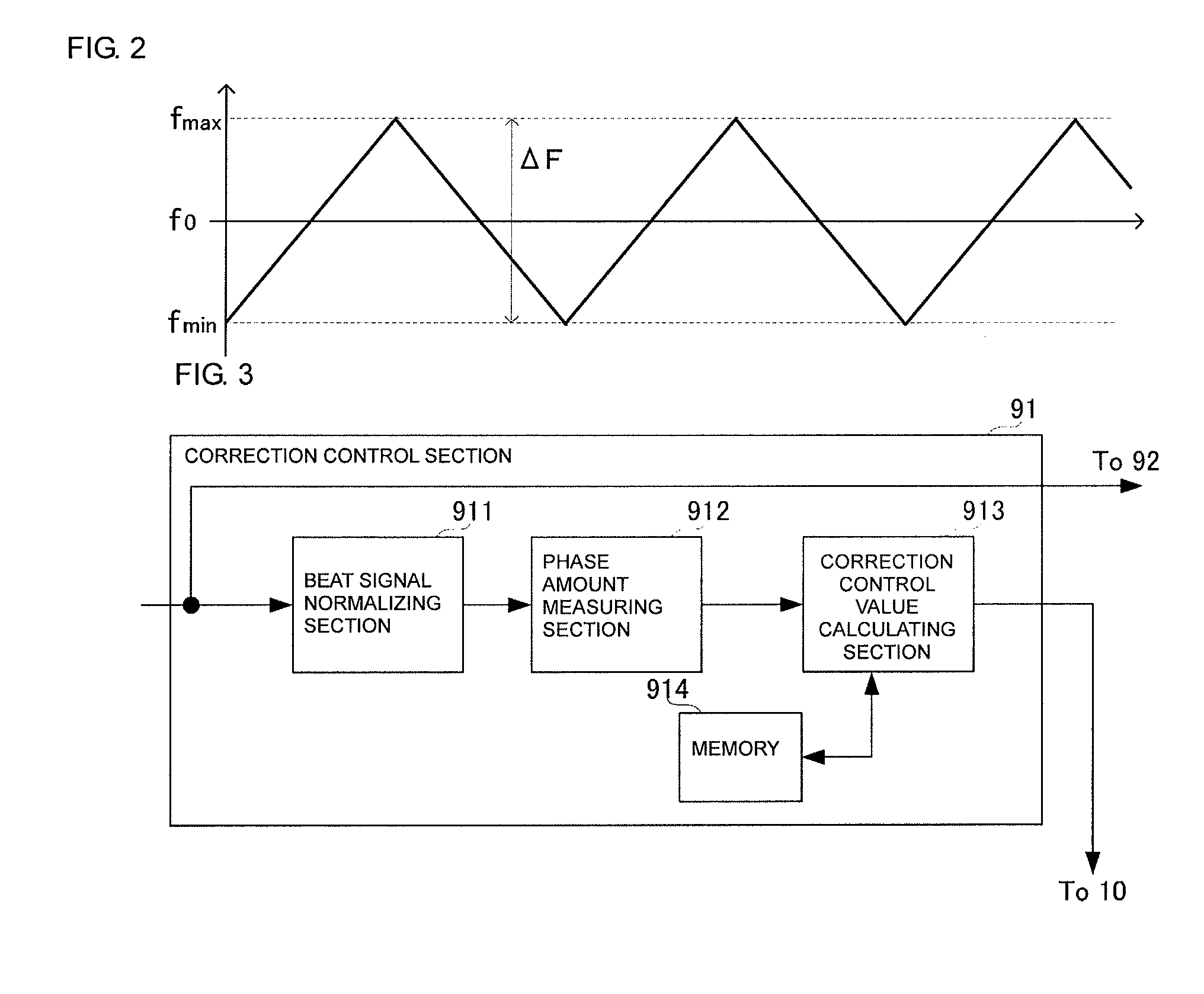
[0047]FIG. 2 is a waveform chart of a transmission signal in the radar apparatus according to the first embodiment.

[0048]As illustrated in FIG. 1, the radar apparatus according to this embodiment includes a transmission control section 10, a DA converter 11, a VCO (voltage control oscillator) 1, a coupler 2, a transmitting antenna 3, a receiving antenna 4, a mixer 5, an antialiasing filter 6, an IF amplification circuit 7, an AD converter 8, and a signal processing section 9.

[0049]The transmission control section 10 generates transmission control data for a transmission signal having a frequency that changes in the form of a triangular wave on the time base, as illustrated in FIG. 2, (hereinafter referred to as a “triangular-wave transmission signal”). ...

second embodiment

[0084]A radar apparatus will be described below with reference to the drawings.

[0085]FIG. 8 is a block diagram illustrating a primary configuration of the radar apparatus according to the second embodiment.

[0086]FIG. 9 is a block diagram illustrating a primary configuration of a correction control section 95 in the second embodiment.

[0087]FIG. 10 is a flowchart illustrating a processing flow executed in the correction control section 95 in the second embodiment.

[0088]The radar apparatus according to the second embodiment includes a coupler 22 between a coupler 21 corresponding to the coupler 2 in the first embodiment and a mixer 51 corresponding to the mixer 5 in the first embodiment. Further, the radar apparatus according to the second embodiment includes a coupler 23 between the receiving antenna 4 and the mixer 51. A π / 2 phase shifter 25 is connected to a branch signal output terminal of the coupler 22. A mixer 52 is connected to a branch signal output terminal of the coupler 23...

third embodiment

[0101]A radar apparatus will be described below with reference to the drawings.

[0102]FIGS. 11(A) and 11(B) are block diagrams illustrating a primary configuration of the radar apparatus according to the third embodiment.

[0103]FIG. 12 is a flowchart illustrating a processing flow executed in a correction control section 91 in the third embodiment.

[0104]The radar apparatus according to the third embodiment has the same configuration as the radar apparatus according to the first embodiment except that the former differs only in configuration of the signal processing section 9 from the latter.

[0105]In the radar apparatus according to the third embodiment, the distance to the target 100, which has been calculated by the distance / speed calculating section 94, is applied to the correction control section 91. The distance applied to the correction control section 91 is also applied to the correction control value calculating section 913.

[0106]The third embodiment is described in connection...


PUM


Abstract

A beat signal normalizing section in a correction control section normalizes a group of sampling data of an input beat signal in one processing group. A phase amount measuring section calculates an amount of phase change of each sampling data. A correction control value calculating section compares the actually measured amount of phase change of each sampling data with an ideal amount of phase change of each sampling data and generates correction voltage data such that the actually measured amount of phase change matches with the ideal amount of phase change. Correction control data provided as the correction voltage data at each sampling time is applied to a transmission control section. The transmission control section generates transmission control data based on the correction control data and applies the transmission control data to a VCO through a DAC.

Description

CROSS REFERENCE TO RELATED APPLICATIONS[0001]The present application is a continuation of International Application No. PCT / JP2007 / 073049, filed Nov. 29, 2007, which claims priority to Japanese Patent Application No. JP2006-322980, filed Dec. 11, 2006, the entire contents of each of these applications being incorporated herein by reference in their entirety.FIELD OF THE INVENTION[0002]The present invention relates to a radar apparatus for transmitting electric waves to a detection area and detecting a target (object) based on waves reflected by the target upon impingement of the transmitted waves against the target, and more particularly to a radar apparatus in which a frequency of the transmitted waves is changed over time within a predetermined frequency range.BACKGROUND OF THE INVENTION[0003]Hitherto, various radar apparatuses have been proposed which are disposed, for example, in front portions of automobiles, and which transmit transmission waves to a predetermined detection ar...

Claims


Application Information

Patent Timeline
Patent Type & Authority Patents(United States)
IPC IPC(8): G01S13/34G01S7/40
CPCG01S7/4008G01S13/345
Inventor NAKANISHI, MOTOI
Owner MURATA MFG CO LTD
Features
  • R&D
  • Intellectual Property
  • Life Sciences
  • Materials
  • Tech Scout
  • Unparalleled Data Quality
  • Higher Quality Content
  • 60% Fewer Hallucinations
Learn More