Method of calibrating light delivery systems, light delivery systems and radiometer for use therewith

a technology of light delivery system and radiometer, which is applied in the direction of photometry, x-ray tubes with very high current, radiation therapy, etc., can solve the problems of long exposure time needed to properly cure the adhesive, undesirable differences between the output intensity levels, and the decrease in the intensity of the light produced by the light source over the life of the sour

Active Publication Date: 2010-11-16
EXCELITAS CANADA
View PDF14 Cites 13 Cited by
  • Summary
  • Abstract
  • Description
  • Claims
  • Application Information

AI Technical Summary

Problems solved by technology

It is also known that the intensity of the light produced by the light source may decrease over the life of the source or be affected by environmental conditions.
If the light source degrades, so will the amount of light energy being delivered to cure the adhesive and therefore a longer exposure time is needed to properly cure the adhesive.
In a production setting, there may be many light curing systems and hence many radiometers, especially when the substitutes are included, Calibration of these multiple radiometers is not only time-consuming but also may lead to undesirable differences between the output intensity levels.
Different rates of degradation of the light sources, and transmission losses of the light guides, the different responses of light sources to environmental conditions, as well as different rates of drift of the radiometers, may lead to undesirable differences between output intensity levels of the different light curing systems.
The problem is compounded where several light curing systems are preset to the same output intensity or irradiance setting.

Method used


Image

  • Method of calibrating light delivery systems, light delivery systems and radiometer for use therewith
  • Method of calibrating light delivery systems, light delivery systems and radiometer for use therewith
  • Method of calibrating light delivery systems, light delivery systems and radiometer for use therewith

Examples


Embodiment Construction

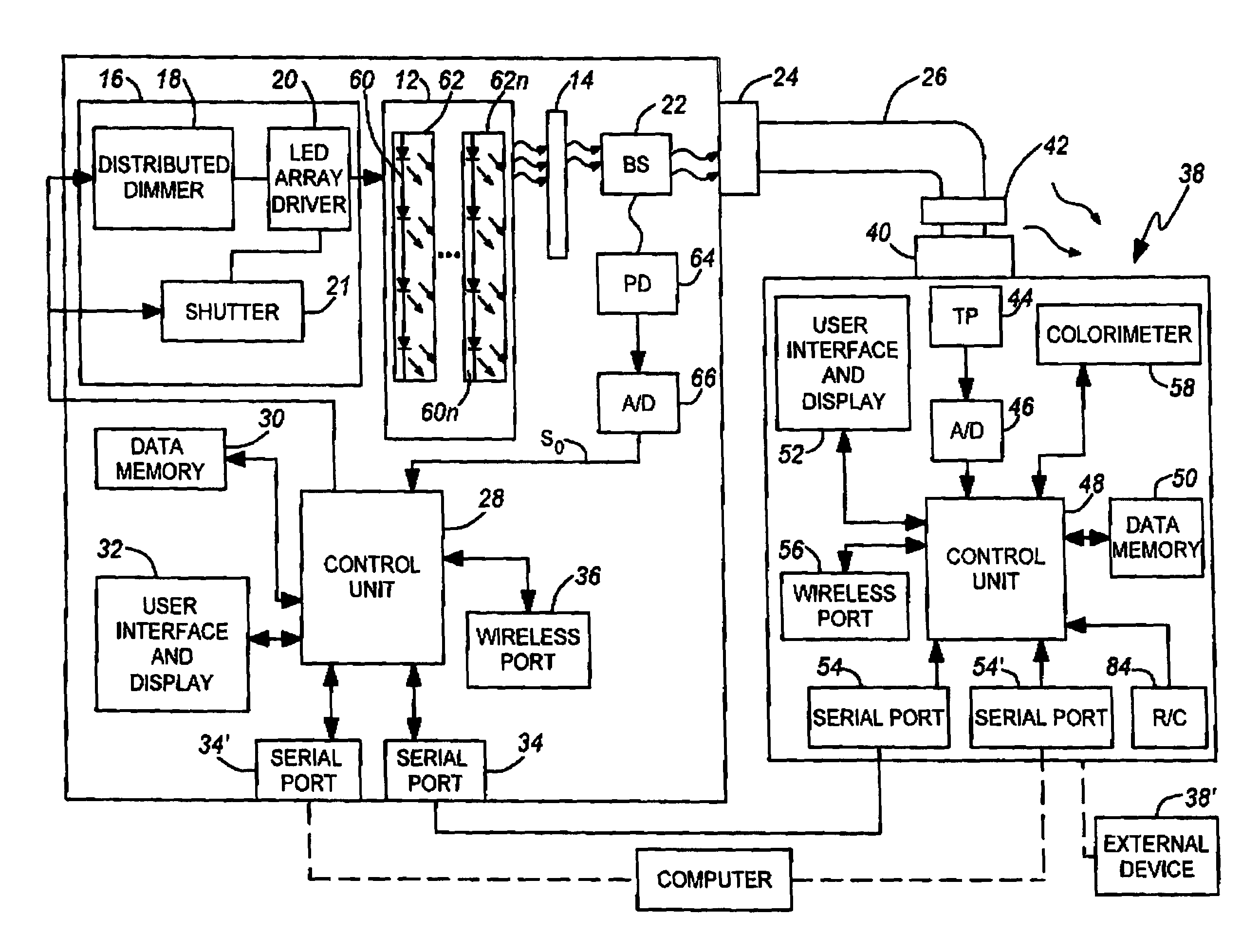
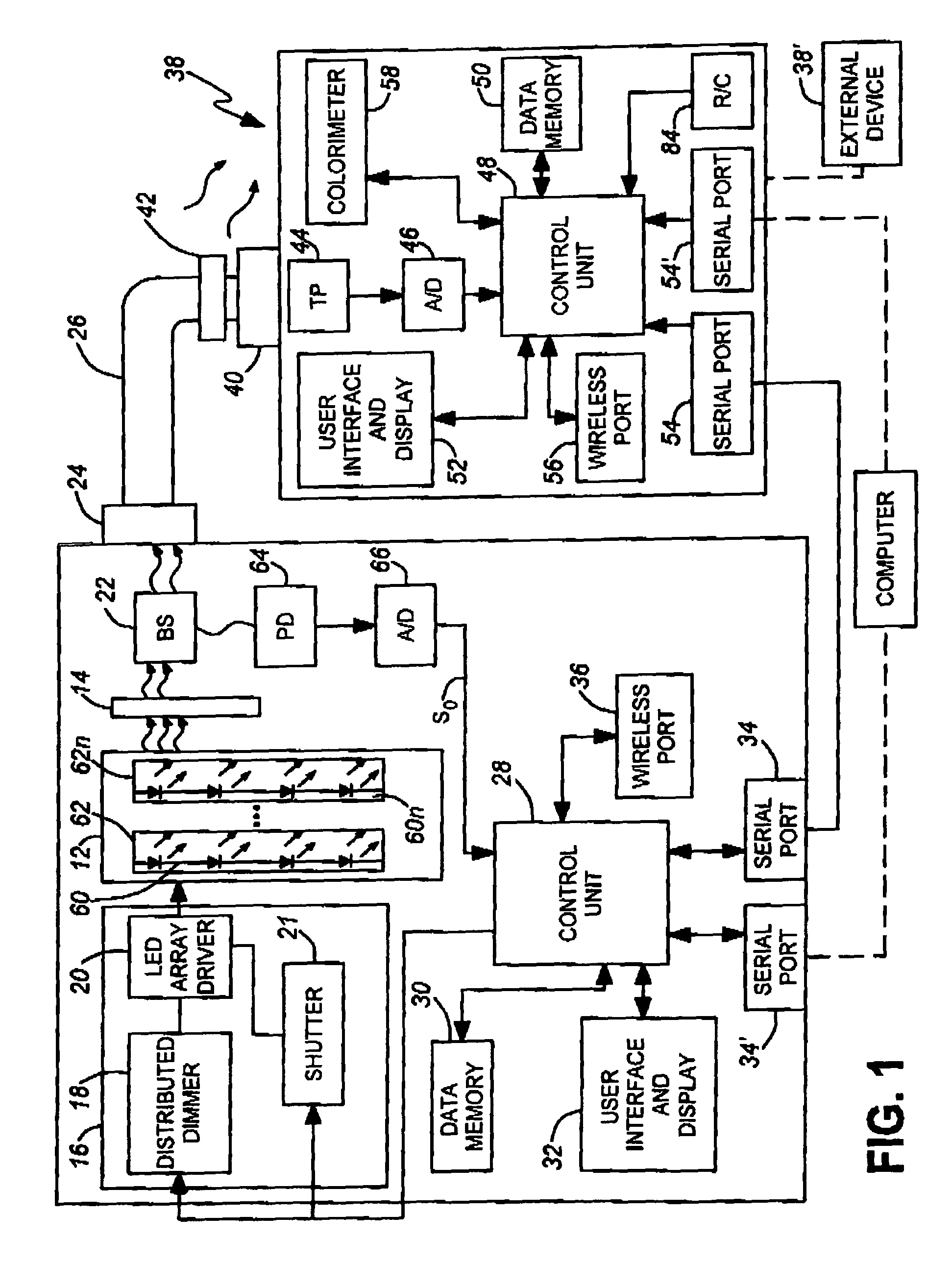
[0057]FIG. 1 illustrates a light delivery system comprising a light delivery device 10, for example a UV printing or spot airing device, which, typically, is one of a set of similar such light delivery devices, perhaps disposed along the same production line. The light delivery device 10 comprises a light source unit 12, a bandpass filter 14, an intensity control module 16. The intensity control module 16 comprises a LED array driver 20, comprising a distributed dimmer module 18, and an electronic shutter control 21. Also provided at the output of the bandpass filter 14 are abeam splitter 22 and an output port 24 to which, in use, a light delivery means 26, specifically a light guide, can be connected. In this embodiment, the light source unit 12 comprises a UV LED light source comprising a plurality (n) of LED arrays 60, . . . 60n, each in a reflective LED array housing 62 . . . 62n. Each UV LED array comprises an array of a plurality of individual LEDs, and the LED array driver an...


PUM

PropertyMeasurementUnit
irradianceaaaaaaaaaa
irradiance levelaaaaaaaaaa
colouraaaaaaaaaa

Abstract

In a method of calibrating a light delivery device (10) having a solid state light source (12), for example comprising LEDs of an LED array, and an intensity control unit (16) comprising LED array driver and a dimmer module for generating a control signal for controlling at least the intensity of the light source, the light source is temporarily connected by a light guide (24; 24, 26) to a radiometer (38) for detecting irradiance of the delivered light. The light delivery device has a memory (30) for storing control signal parameters and associated radiance levels. The light delivery device is calibrated by adjusting the control signal parameters, e.g. a PWM duty cycle of a control signal to each of a series of predetermined settings, obtaining from the radiometer a corresponding series of delivered light irradiance levels measured thereby, storing the irradiance levels and associated control signal parameters in memory, and applying a best fit algorithm to the irradiance measurements and control signal parameters. Thereafter, a desired irradiate level can be set by selecting the best fit control signal parameters, such as duty cycle of a PWM control or other parameters. Output intensity levels may be measured at the same time as the irradiance levels and used to compensate for light source output level changes when setting a desired irradiance level.

Description

CROSS REFERENCE TO RELATED APPLICATION[0001]This application is a Continuation-in-Part of U.S. patent application Ser. No. 11 / 312,462 filed Dec. 21, 2005 now U.S Pat. No. 7,335,901 and claims priority from U.S. Provisional patent application No. 60 / 638,344 filed Dec. 23, 2004; the entire contents of each these prior applications are incorporated herein by reference.TECHNICAL FIELD[0002]The invention relates to methods of calibrating light delivery systems, to the light delivery systems themselves and to radiometers for use therewith and is especially, but not exclusively, applicable to light delivery systems for printing and curing photosensitive materials including inks, adhesives and other coatings.BACKGROUND ART[0003]As discussed in the background section of U.S. Pat. No. 5,521,392 (Kennedy et al.), commonly owned with the present invention, there are numerous substances which are sensitive to light energy. The substances of interest generally fall into two classes. The first cla...

Claims


Application Information

Patent Timeline
Patent Type & Authority Patents(United States)
IPC IPC(8): G02F1/03
CPCG01J1/02G01J1/0228G01J1/0271G01J1/08G01J1/32G01J1/42H05B33/086H05B33/0869A61N5/062G01J2001/0481G01J2001/4252H05B45/22H05B45/20
Inventor KAYSER, ROYSONG, YUMACDONALD, MITCHELL WADE
Owner EXCELITAS CANADA
Why Eureka
Try Eureka