Heat processing apparatus, heat processing method, computer program and storage medium

a heat processing apparatus and heat processing technology, applied in the direction of adaptive control, electric controllers, instruments, etc., can solve the problems of temperature drop, insufficient power supply of each heater b>103/b>, and difficulty in stabilizing the temperature of the inner wall of the inner tube b>100, etc., to achieve rapid temperature stabilization

Active Publication Date: 2010-11-16
TOKYO ELECTRON LTD
View PDF9 Cites 2 Cited by
  • Summary
  • Abstract
  • Description
  • Claims
  • Application Information

AI Technical Summary

Benefits of technology

[0035]According to the present invention, the external temperature detecting section is provided outside the reaction vessel, and the inner wall temperature of the reaction vessel is predicted, based on the command value of the power to be supplied to the heating means. The step of using the prediction value of the inner wall temperature, as a main object to be controlled, upon the loading, is included in the calculation of the command value of the power to be supplied to the heating means. Change of the inner wall temperature of the reaction vessel upon the loading can be suppressed, as such film peeling caused by, for example, heat shock, can be significantly suppressed.
[0036]Subsequently to the step described above, the calculation includes the step of using the combined value including the prediction value of the inner wall temperature and the detection value of the external detecting section, as an object to be controlled, and then using the detection value of the external temperature detecting section, as a main object to be controlled. Consequently, the gradual or mild change from the prediction value of the inner wall temperature into the detection value of the external temperature detecting section as the main object to be controlled can suppress the so-called overshoot that the temperature in the reaction vessel significantly exceeds a setting temperature due to application of excessive power to the heating means, after closing the reaction vessel by using the cover on the end point of the loading. As such, significantly rapid temperature stabilization can be achieved.

Problems solved by technology

In addition, because relatively low temperature wafers W are loaded in the wafer boat 104, it is difficult to stabilize the temperature of the inner wall of the inner tube 100 upon the loading.
Thus, the power supply to each heater 103 tends to be insufficient, as such increasing the temperature drop of the inner wall.
While such a temperature drop can be addressed by controlling the detected lower temperature value to be returned to a desired value, the power supply to each heater 103 may tend to be unduly large, as such the temperature of the inner wall is likely to be excessively high.
However, this is not practical because the entire body of the inner tube 100 must be exchanged if any one of the temperature detecting sections 106 is disconnected.
If significant temperature change occurs in the inner wall of the inner tube 100, film peeling may tend to be caused by difference of coefficients of thermal expansion between the material of the reactions vessel, for example, quartz, and a thin film deposited on the inner wall, resulting in contamination due to particles or particle contamination.
However, because of a significantly greater difference of coefficients of thermal expansion between the silicon nitride film and quartz, film peeling is likely to occur due to temperature change of the inner wall.
Additionally, because of current tendency of designing a further miniaturized and thinner-filmed semiconductor device, the acceptable limit for particles has become quite critical.
Therefore, phenomena that have not been considered significantly problematic tends to be conspicuous as factors of deteriorating the yield.

Method used


Image

  • Heat processing apparatus, heat processing method, computer program and storage medium
  • Heat processing apparatus, heat processing method, computer program and storage medium
  • Heat processing apparatus, heat processing method, computer program and storage medium

Examples


examples

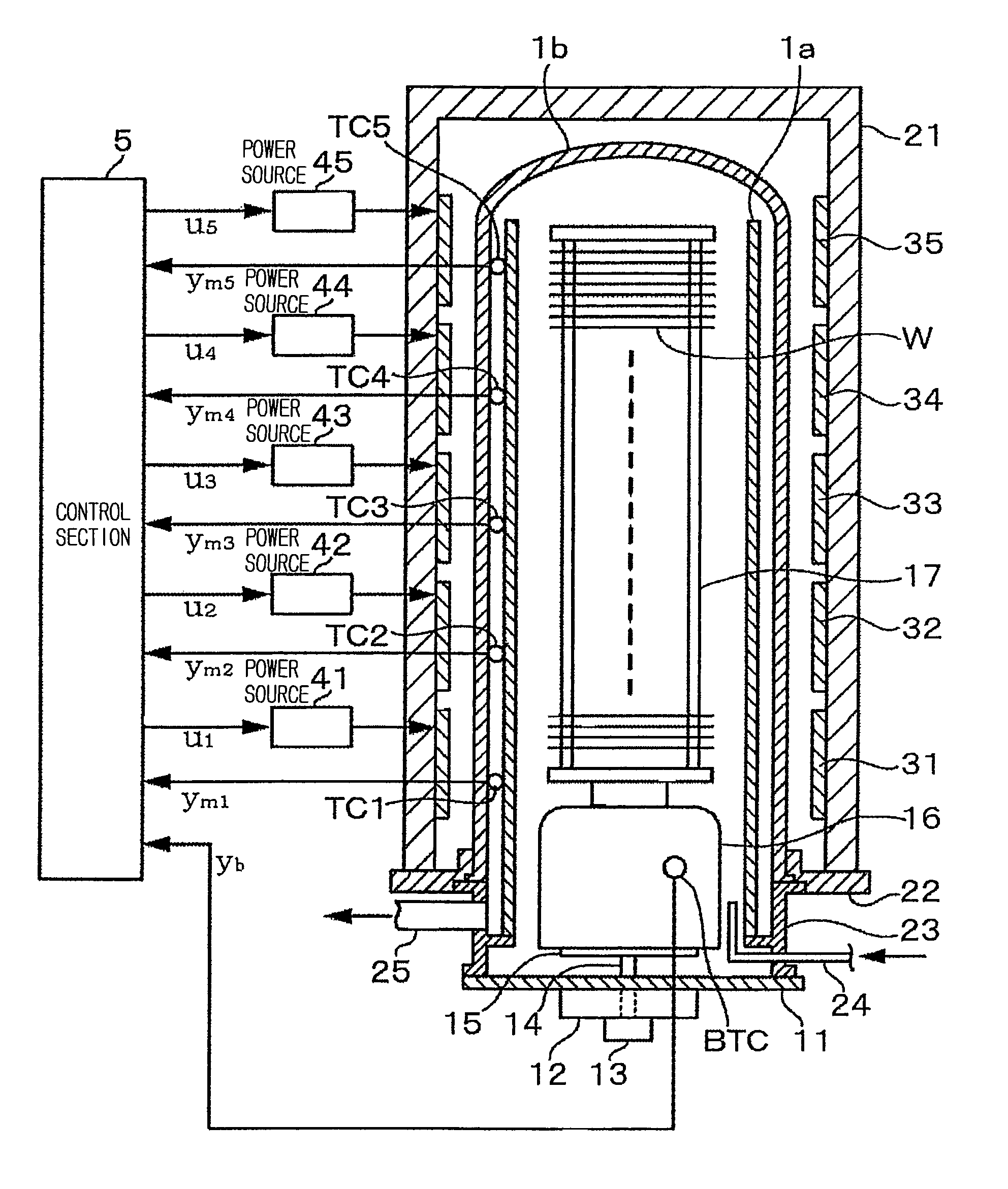
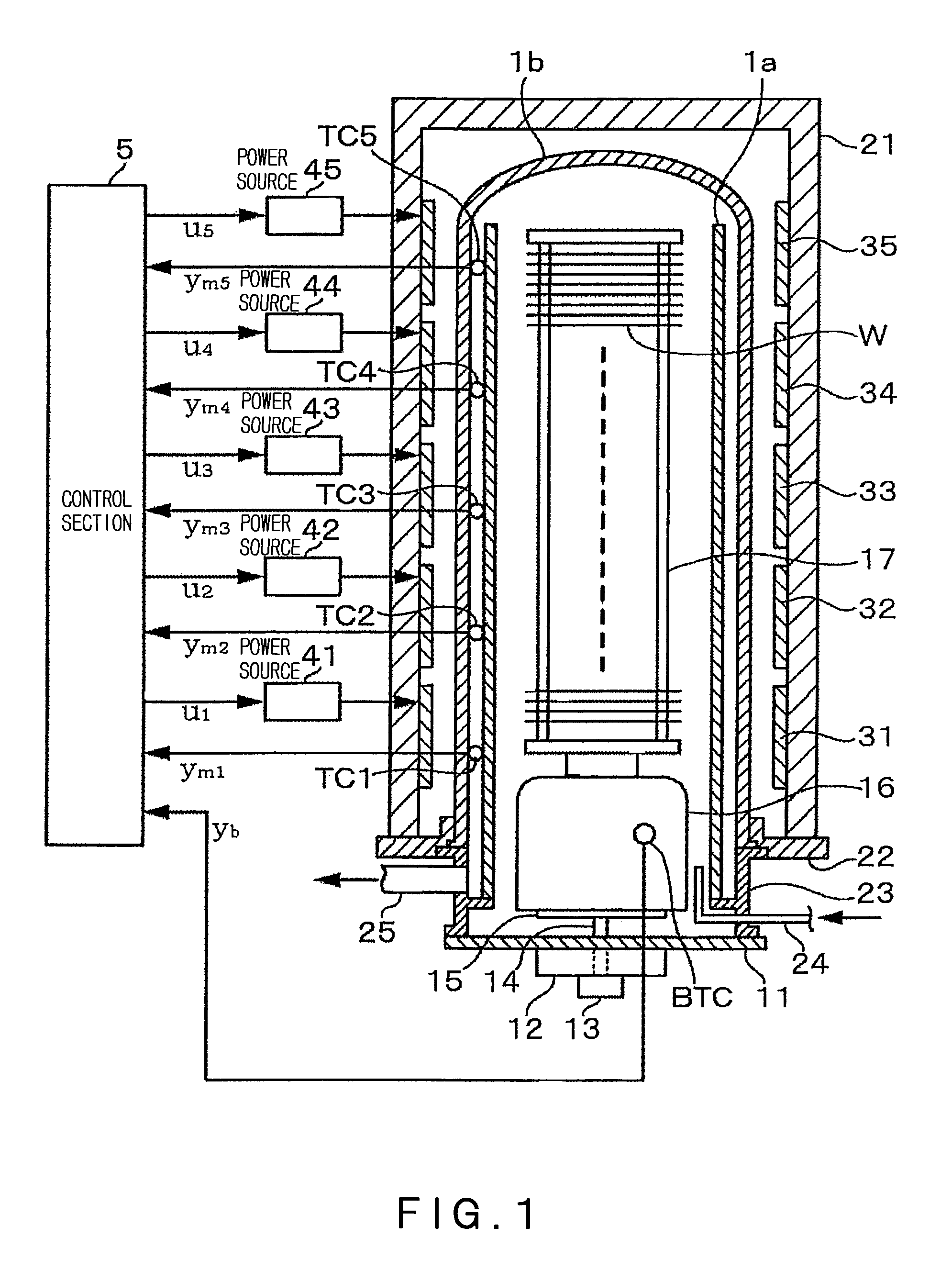
[0045]FIG. 1 shows the entire construction of one embodiment, in which the present invention is applied to a vertical-type heat processing apparatus. First, the entire construction of the vertical-type heat processing apparatus will be described in brief. The vertical-type heat processing apparatus includes, for example, a quartz tube having a double tube structure, comprising an inner quartz tube 1a opening at both ends and an outer quartz tube 1b closed at its top end. In this example, since the inner wall 1a divides the heat processing atmosphere, a reaction vessel corresponds to the inner tube 1a. Around the outer tube 1b, a tubular thermal insulation layer 21 is provided, being fixed to a base body 22. On the inner wall of the thermal insulation layer 21, a plurality of heaters each comprising a resistance heating material are provided to be separately arranged, for example, in the vertical direction. In this example, the number of the divided stages of the heaters is, for exam...


PUM

PropertyMeasurementUnit
temperatureaaaaaaaaaa
poweraaaaaaaaaa

Abstract

In a vertical-type heat processing apparatus, it is intended to stabilize the temperature of an inner wall of the reaction vessel upon loading as well as to reduce particle contamination, for example, by suppressing peeling of films attached to the inner wall. An inner wall temperature sensor is attached, in advance, to the inner wall of the reaction vessel, so as to obtain each time series data of detection values of the inner wall temperature sensor and a command value of power to be supplied to heating means. The inner wall temperature is predicted from the command value of the power obtained just before, based on the data, during an initial time of loading, so as to use the predicted value of the inner wall temperature as an object to be controlled. Thereafter, around the end time of loading, the object to be controlled is gradually changed into a temperature detection value of a temperature detecting section provided outside the reaction vessel, so as to be completely changed over time into the temperature detection value.

Description

CROSS REFERENCE TO RELATED APPLICATIONS[0001]This application is based upon the prior Japanese Patent Application No. 2006-221665 filed on Aug. 15, 2006, the entire contents of which are incorporated herein by reference.BACKGROUND OF THE INVENTION[0002]1. Field of the Invention[0003]The present invention relates to a technical field of temperature control for a heat processing apparatus, for example, a vertical-type heat processing apparatus, for carrying out a heat process, after placing a plurality of substrates, such as semiconductor wafers, on a substrate holding tool and carrying it into a reaction vessel.[0004]2. Background Art[0005]There is known a vertical-type heat processing apparatus to be used for providing a heat process, such as film forming due to CVD, oxidation, diffusion and the like, to semiconductor wafers (hereinafter, referred to as “wafers”) in a batch manner. This vertical-type heat processing apparatus includes a heating furnace and a vertical-type reaction v...

Claims


Application Information

Patent Timeline
Patent Type & Authority Patents(United States)
IPC IPC(8): G06F19/00C23C16/46C23C16/52H01L21/22H01L21/31
CPCG05B11/42G05B13/048H01L21/324
Inventor KATAOKA, YUKIYUKIO, TOJO
Owner TOKYO ELECTRON LTD
Why Eureka
Try Eureka