Tools for use with robotic systems

Active Publication Date: 2010-11-23
SCI APPL INT CORP +1
View PDF8 Cites 35 Cited by
  • Summary
  • Abstract
  • Description
  • Claims
  • Application Information

AI Technical Summary

Benefits of technology

[0009]The embodiments of the present invention facilitate disabling explosives while minimizing risk to EOD personnel. In a first exemplary embodiment, a system for placing a gun barrel within firing distance of a target is described. The system comprises: a remote controlled vehicle including a remotely controllable arm; a first componen

Problems solved by technology

A major obstacle to successfully disabling explosives is the risk posed to EOD personnel.
Further, current configurations for placing disruptors

Method used


Image

  • Tools for use with robotic systems
  • Tools for use with robotic systems
  • Tools for use with robotic systems

Examples


Embodiment Construction

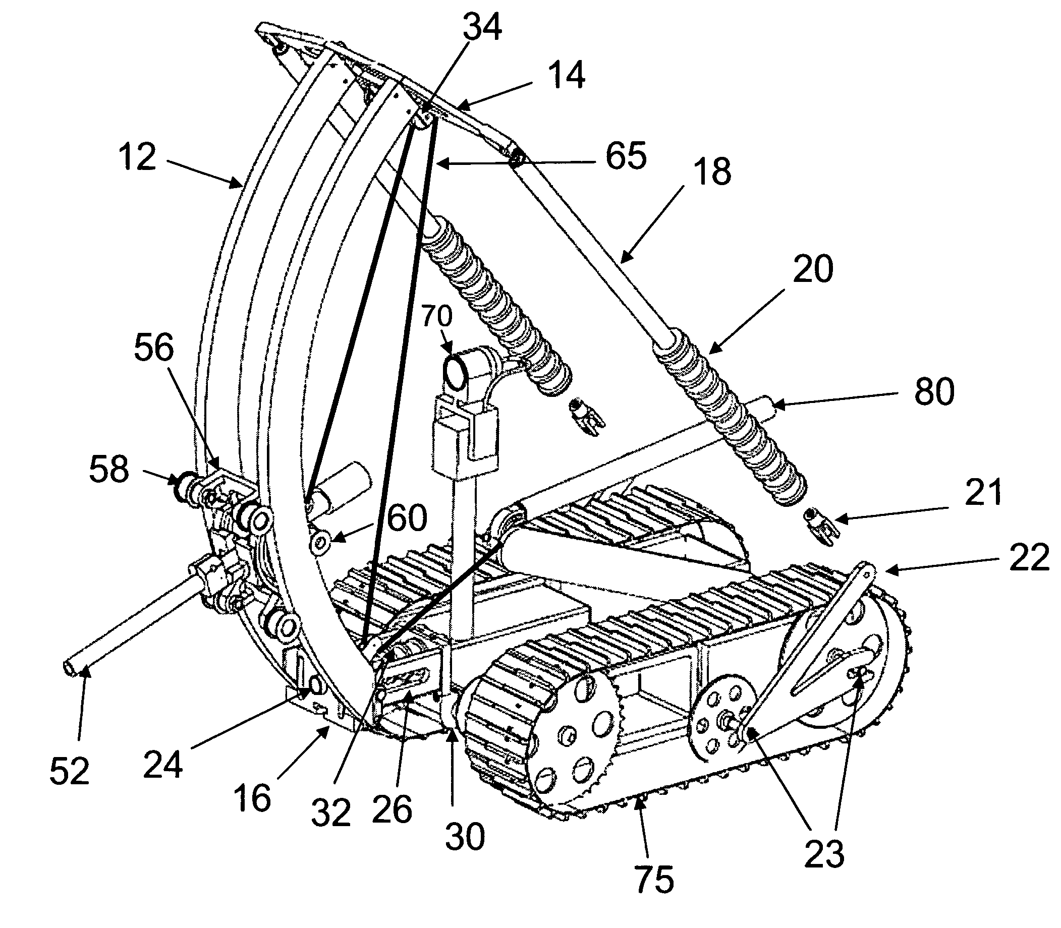
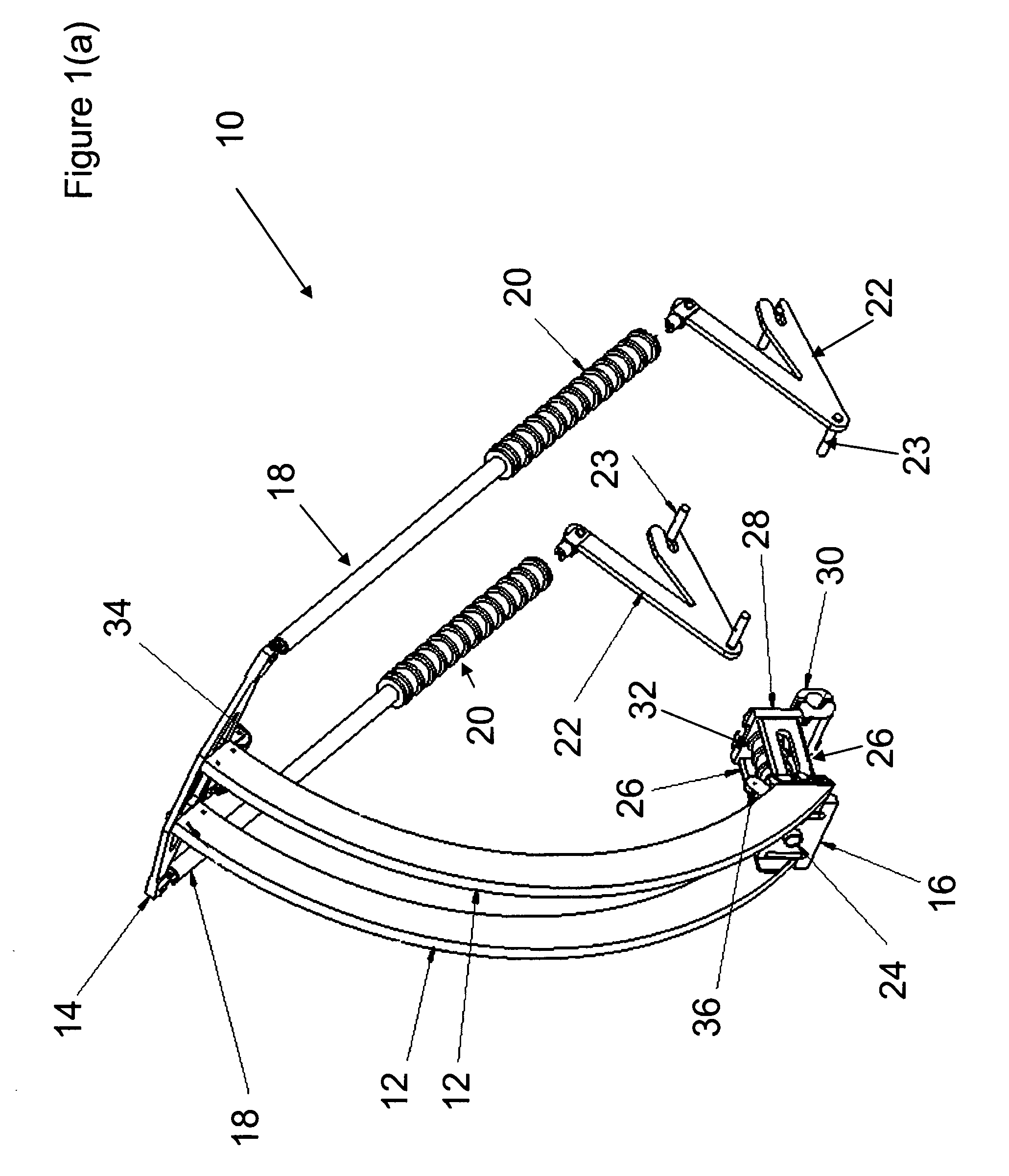
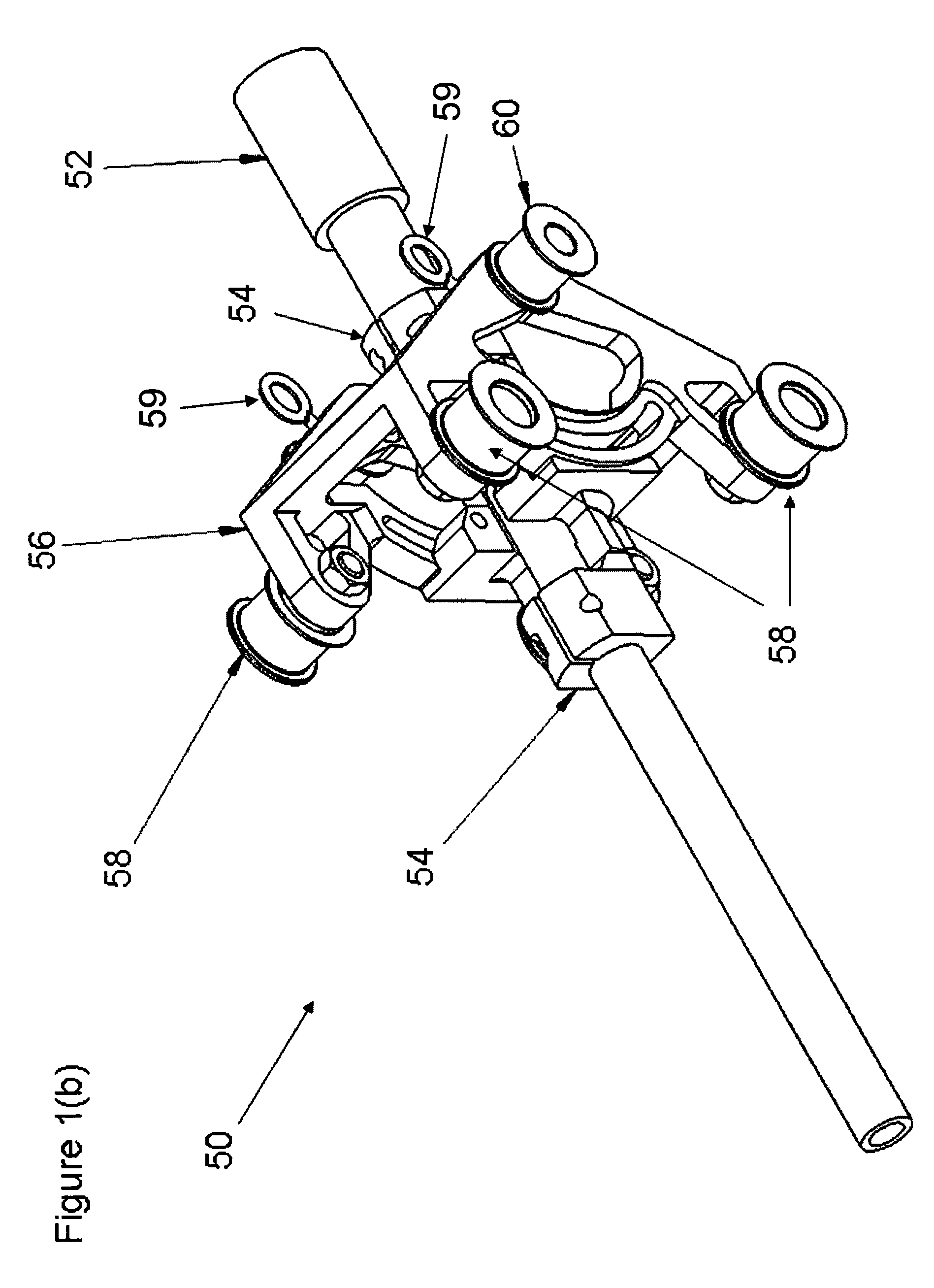
[0022]FIGS. 1(a) and 1(b) illustrate a tool for attaching a pan disruptor to Foster Miller's Talon robot. A pan disruptor is essentially a gun that can fire several different types of projectiles, e.g., water, bullets, clay, etc. depending on the need. The Foster Miller Talon may be fitted with the pan disruptor described in the preferred embodiment either directly or via a trailer skid assembly as described herein with respect to FIGS. 2(a) through 2(c).

[0023]Referring to FIG. 1(a), a first component 10 of the pan disruptor assembly includes rails 12 attached directly to a top shock support 14 and front support block 16. Top shock support 14 is attached to a first end of upper recoil supports 18 which include shock absorbers 20. The second end of the upper recoil supports 18 are attached to rear axle braces 22 including rear axle support pins 23 (four pins shown). Rear axle support pins 23 are used to attach component 10 to the Talon robot (see FIG. 1(c)). The front support block 1...


PUM


Abstract

Systems are described herein for remotely aligning and placing disruptive devices at or near suspicious targets such as suspected improvised explosive devices (IEDs). In particular, tools connected to remotely controllable robots include disruptor guns for firing disruptive materials at the targets and disruptive devices filled with explosive materials, e.g., water, for controllably detonating or disrupting the detonation of the targets when placed in close proximity thereto.

Description

GOVERNMENT RIGHTS IN INVENTION[0001]This invention was made with Government support under contract no. N66001-06-D-5021, DO 0010 awarded by the Department of the Navy. The Government has certain rights in this invention.BACKGROUND OF THE INVENTION[0002]1. Field of the Invention[0003]The present invention relates generally to the field of explosive ordinance disposal (EOD) and more particularly to EOD using robotic devices with various disposal attachments thereon.[0004]2. Description of the Related Art[0005]There are many situations in which police, military personnel or others require the ability to dispose of or render safe an explosive device, e.g., landmines, improvised explosive devices (IEDs), CBRN (chemical / biological / radiological / nuclear) devices, etc. while minimizing risk to themselves and others. Remotely operated robots have been developed to investigate potential explosive devices and in some cases are used to disable the devices or to detonate in a controlled manner. E...

Claims


Application Information

Patent Timeline
IPC IPC(8): F41A23/00
CPCF41A23/28F41A23/56F41A25/00F41A27/24F41H7/005F41H11/16
Inventor GARDNER, CHRISTOPHER W.STRATTON, BENJAMIN V.ROBBINS, AARON
Owner SCI APPL INT CORP
Why Eureka
Try Eureka