Power tool

a technology of power tools and handle parts, applied in the field of power tools, can solve the problems of large initial load, insufficient absorbing of low vibration area of power tools, and accuracy errors, and achieve the effects of improving workability of power tools, reducing backlash, and reducing the number of power tools

Active Publication Date: 2010-11-23
KOKI HLDG CO LTD
View PDF29 Cites 20 Cited by
  • Summary
  • Abstract
  • Description
  • Claims
  • Application Information

AI Technical Summary

Benefits of technology

[0007]Therefore, the invention has an object to provide a power tool which can reduce an initial load to be applied to an elastic unit in an initial state and absorb vibration in the low vibration area efficiently.
[0022]According to an eighth aspect of the invention, the power tool includes the motor accommodated in the housing; the reciprocation converting part which converts rotation of the motor into reciprocating motion; and the tip tool which is attached to a leading end side of the housing, and drives by the reciprocating motion of the reciprocation converting part. Further, the reciprocation converting part includes the cylinder, the piston provided at the inner periphery of the cylinder slidably, the motion converting part which converts rotational drive force of the electric motor into reciprocating motion of the piston, and the striker which is driven by the reciprocating motion of the piston. Therefore, the vibration in the low vibration area generated by the drive of the striker in the initial operation can be damped effectively by the rotation urging unit and the elastic unit, and workability of the power tool can be improved.

Problems solved by technology

However, in case that reduction of the initial load of the coil spring (reduction of free length of the coil spring) is attempted, backlash can be produced by accuracy error thereof.
To the contrary, in case that it is attempted to prevent the backlash from being produced, the initial load cannot help being set large.
Accordingly, since the initial load of the coil spring is large in the initial state after all, the vibration in the low vibration area of the power tool cannot be absorbed sufficiently, so that workability lowers.

Method used


Image

  • Power tool
  • Power tool
  • Power tool

Examples


Embodiment Construction

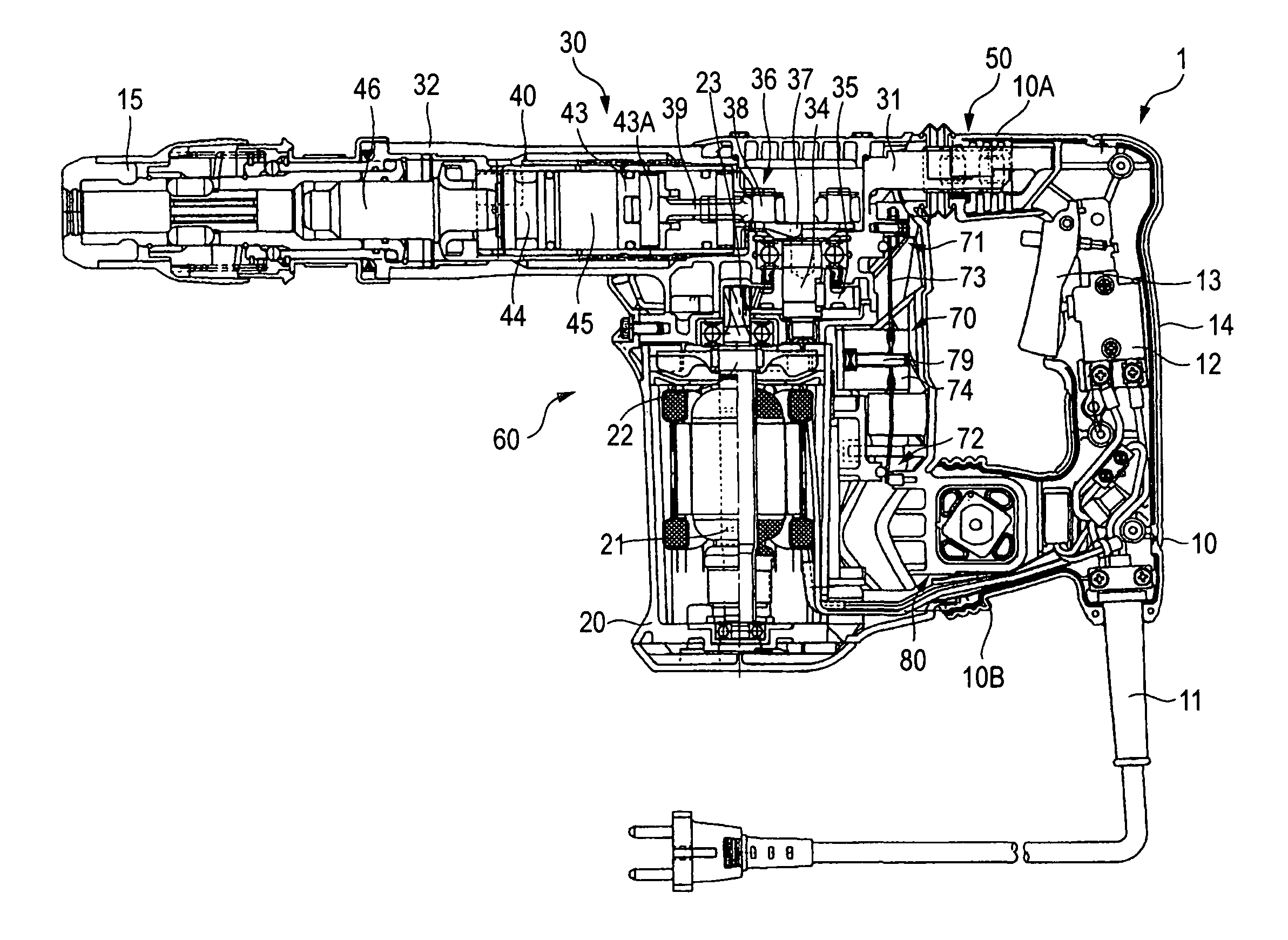
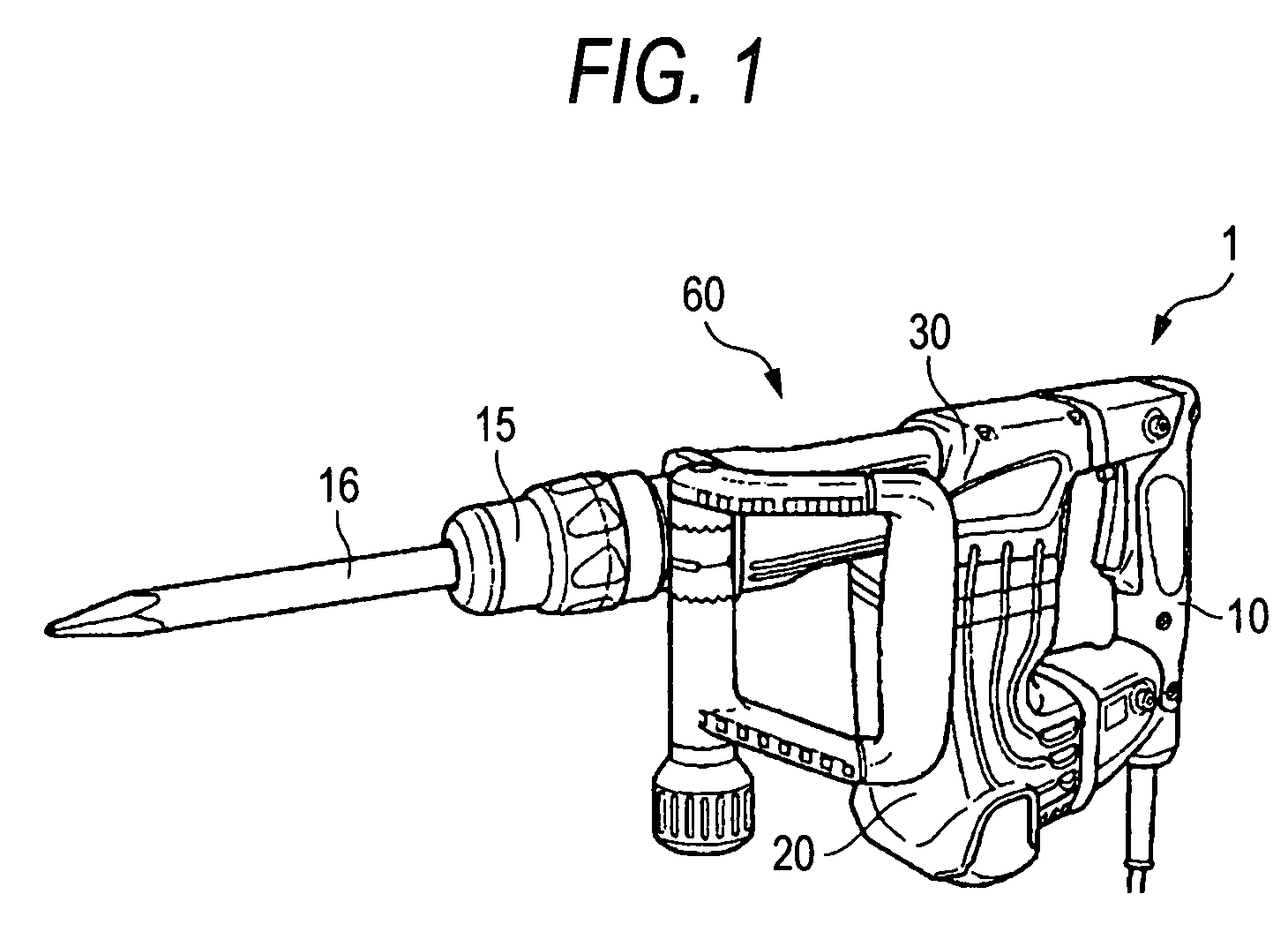
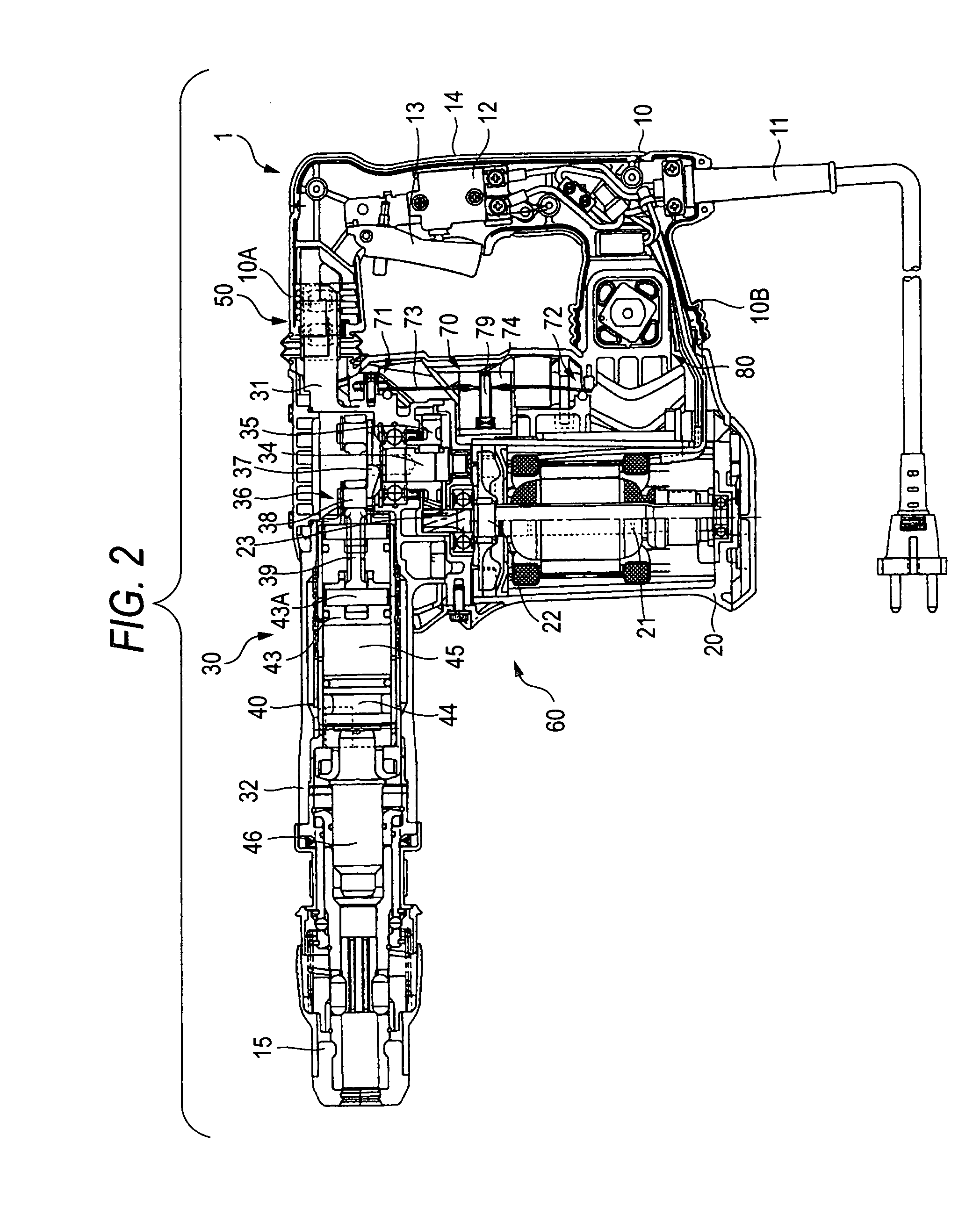
[0044]A first embodiment in which the power tool of the invention is applied to a hammer tool will be described with reference to FIGS. 1 to 5. With the left side in FIGS. 1 and 2 as a leading end side of a hammer tool 1 and with the right left therein as a rear end side thereof, the embodiment will be described below. The hammer tool 1 includes a handle portion 10, and a tool body 60 composed of a motor housing 20 and a gear housing 30.

[0045]As shown in FIG. 2, to the handle portion 10, a power cable 11 is attached, and a switch mechanism 12 is included in the handle portion 10. To the switch mechanism 12, a trigger 13 which can be operated by a user is mechanically connected. The power cable 11, by connecting the switch mechanism to a not-shown external power source and operating the trigger 13, can switch connection and disconnection between an electric motor 21 described later and the external power source. Further, the handle portion 10 has a grip portion 14 which the user grip...


PUM


Abstract

An elastic unit includes a transatory unit including a first elastic support member, a second elastic support member and not-shown four round bar-shaped elastic bodies made of rubber. A rotation urging unit is composed of a Neidhart spring including an outer frame, a shaft, a rotary member, and four rubber rods. The rotary member is in a state where it is rotated at 10° counterclockwise from an initial state. Therefore, the rubber rod deforms upon reception of rolling friction from the outer frame and the rotary member, and the rotation urging unit gives the handle portion the urging power by which the handle portion is rotated so that one end of the handle portion is spaced away from a gear housing 31 in the direction of the handle portion.

Description

CROSS-REFERENCE TO RELATED APPLICATIONS[0001]This application is based on and claims the benefit of priority from the prior Japanese Patent Application No. 2006-166902, filed on Jun. 16, 2006; the entire contents of which are incorporated herein by reference.TECHNICAL FIELD[0002]The present invention relates to a power tool, and particularly to a power tool with a vibration-proof handle.BACKGROUNDDescription of Related Art[0003]Heretofore, a power tool with a vibration-proof handle has been proposed. It is disclosed by, for example JP-A-2005-74573 that a power tool in which an elastic unit is provided between one end of a handle portion and a tool body, and the handle portion is provided rotatably around the other end portion from the tool body side in a direction of the one end. Further, there has been disclosed another power tool in which a handle portion and a tool body coupled to each other are provided, and a power motor and a reciprocation converting part for converting rotati...

Claims


Application Information

Patent Timeline
Patent Type & Authority Patents(United States)
IPC IPC(8): B25D17/04B25D17/24
CPCB25D17/043F16F1/545Y10T16/48
Inventor KIKUCHI, ATSUYUKISUZUURA, TSUKASA
Owner KOKI HLDG CO LTD
Why Eureka
Try Eureka