Electrical plug connector having a slider which connects with a cap upon the slider being inserted into a housing to latch the cap to the housing

a technology of electric plug connector and slider, which is applied in the direction of coupling device connection, coupling/disengagement of coupling parts, electrical apparatus, etc., can solve the problems of loosening or destroying the latching connection between the cap and the housing, and achieves stable connection, high quality, and stable connection

Active Publication Date: 2010-11-23
KOSTAL KONTAKT SYST
View PDF24 Cites 10 Cited by
  • Summary
  • Abstract
  • Description
  • Claims
  • Application Information

AI Technical Summary

Benefits of technology

[0009]The locking hooks are molded to the cap and have the external shape of latching hooks. However, the locking hooks are significantly more rigid and stable than conventional latching hooks. This is because the positively locked connection between the cap and the first housing is produced by insertion of the locking hooks of the cap into the receptacle grooves of the slider surfaces, or, alternatively, the sliding of the receptacle grooves over the locking hooks. In either case, the locking hooks do not have to overcome any latching barrier. An extremely stable connection between the cap and the slider (the slider surfaces) can thereby be created with the locking hooks. This results in an extremely stable connection between the cap and the first housing with this connection being able to withstand large applications of force on the cap from the sides of a wire harness.
[0010]Accordingly, a wire harness can be fixed to the cap without difficulty, which has the advantage that movements of the wire harness, and in particular vibrational motions present in the engine space of a vehicle, are transmitted through the wire harness to the contact elements of the connector after being strongly attenuated. An especially high quality is thereby achieved for the electrical connections made through the connector.

Problems solved by technology

Such force can loosen or destroy the latching connection between the cap and the housing.

Method used


Image

  • Electrical plug connector having a slider which connects with a cap upon the slider being inserted into a housing to latch the cap to the housing
  • Electrical plug connector having a slider which connects with a cap upon the slider being inserted into a housing to latch the cap to the housing
  • Electrical plug connector having a slider which connects with a cap upon the slider being inserted into a housing to latch the cap to the housing

Examples


Embodiment Construction

)

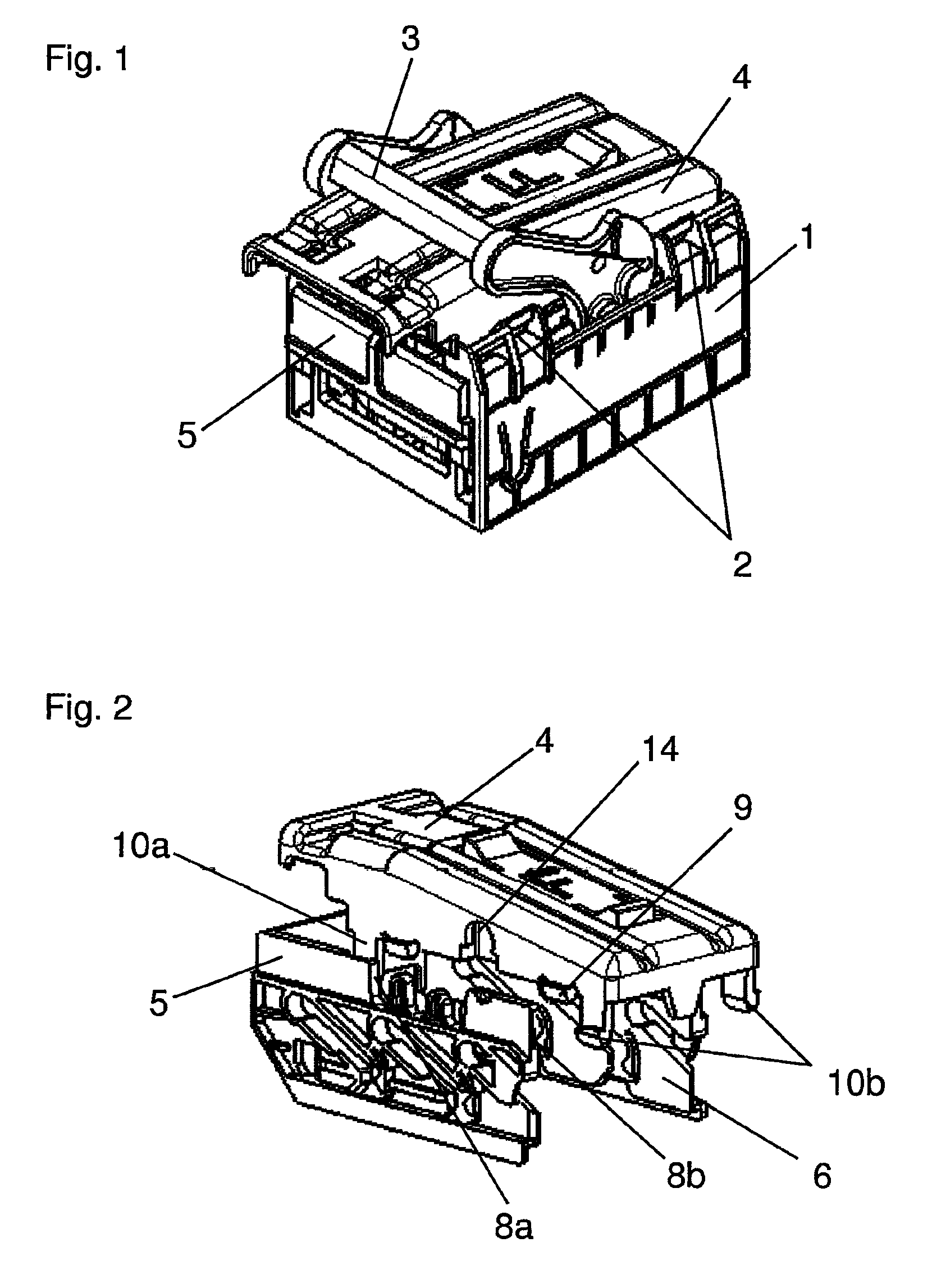
[0020]Referring now to FIG. 1, a first connector housing 1, a slider 5, and a cap 4 of an electrical plug and socket connector in accordance with an embodiment of the present invention are shown. In FIG. 1, cap 4 is in place on first housing 1 and slider 5 is inserted into first housing 1.

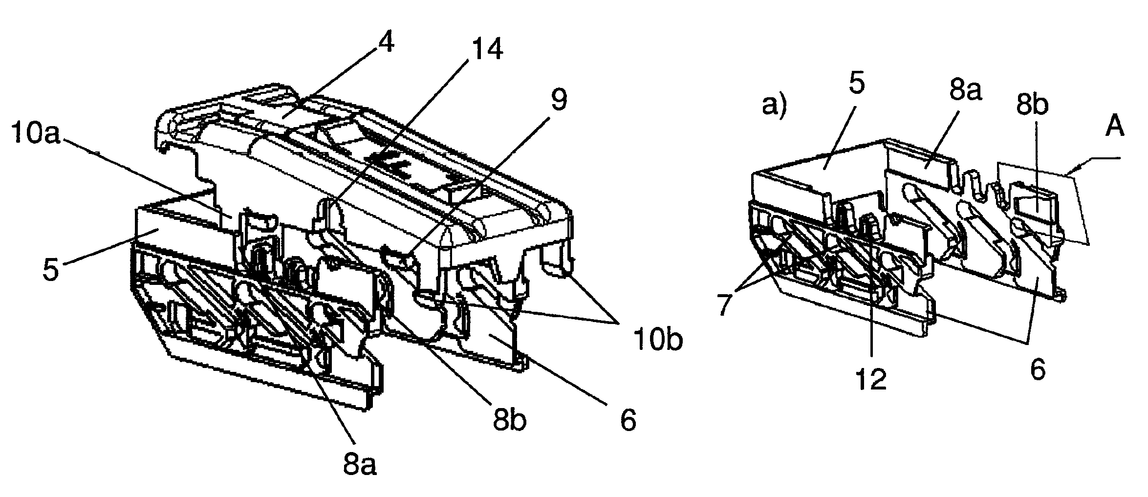
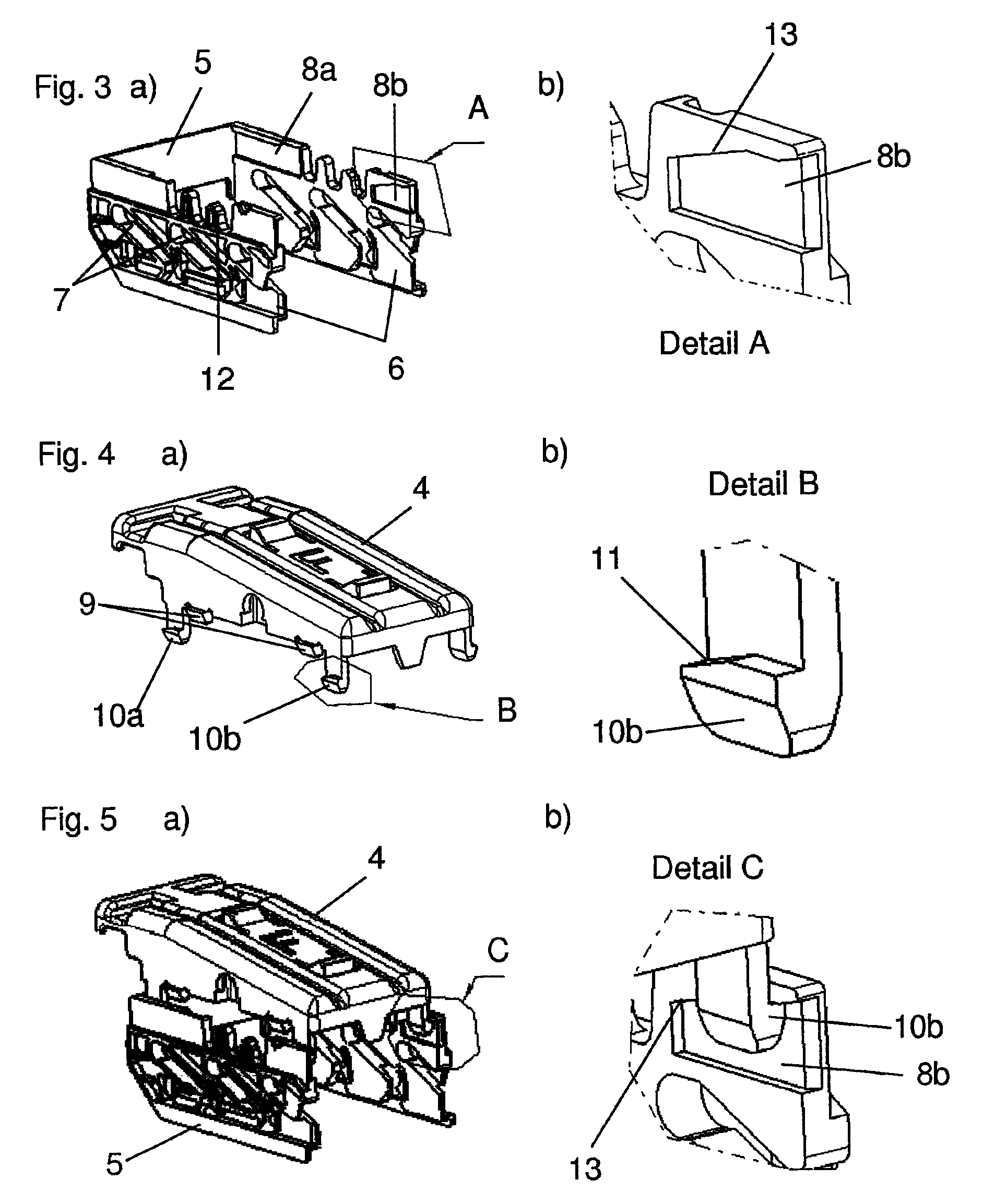
[0021]As shown in FIG. 3a (and in FIGS. 2 and 5), slider 5 includes two parallel slider surfaces 6. Slider surfaces 6 are connected to one another by a single molded connection surface. Slider 5 is thereby molded as a single U-shaped object in which side surfaces form slider surfaces 6.

[0022]As further shown in FIG. 3a, slider surfaces 6 respectively have a plurality of slanted guide grooves 7. In this case, slider surfaces 6 respectively have three slanted guide grooves 7. Slanted guide grooves 7 cooperate in the connection of first housing 1 with cams on a second connector housing of the electrical plug and socket connector. The cams of the second housing slide along guide grooves 7 by an insert...


PUM


Abstract

An electrical plug connector includes a first connector housing, a slider, and a cap. The slider has slider surfaces insertable into the first housing in a direction transverse to a direction of insertion of a second housing to the first housing at a connecting side of the first housing. The slider is connected to the first housing upon the slider surfaces being inserted into the first housing. The cap is on a cap side of the first housing lying opposite to the connecting side of the first housing. The slider surfaces connect with the cap to latch the cap to the cap side of the first housing upon the slider surfaces being inserted into the first housing.

Description

CROSS-REFERENCE TO RELATED APPLICATIONS[0001]This application is a continuation of International Application PCT / EP2007 / 063690, published in German, with an international filing date of Dec. 11, 2007, which claims priority to DE 10 2006 058 680.8, filed Dec. 13, 2006; the disclosures of which are both hereby incorporated by reference.BACKGROUND OF THE INVENTION[0002]1. Field of the Invention[0003]The present invention relates to an electrical plug connector having first and second connector housings and a slider insertable into the first housing in a direction perpendicular to the direction of insertion of the housings onto one another at a connecting side in which one of guide grooves or cams are on the slider and the other one of guide grooves or cams are on the second housing and in which when the slider is inserted into the first housing the cams are guided along the guide grooves and cause a relative displacement of the housings towards each other, and in which a lockable cap c...

Claims


Application Information

Patent Timeline
Patent Type & Authority Patents(United States)
IPC IPC(8): H01R13/62
CPCH01R13/506H01R13/5213H01R13/62977H01R13/62944H01R13/582
Inventor EPE, PETERFOERSTER, THOMAS
Owner KOSTAL KONTAKT SYST
Why Eureka
Try Eureka