Electric motor housing with transmission drive unit interface

a technology of transmission drive and electric motor, which is applied in the direction of generator/motor, mechanical energy handling, mechanical apparatus, etc., can solve the problem that the open electric motor that is used is not suitable for use without a transmission housing, and achieve the effect of simple manner

Inactive Publication Date: 2010-11-23
ROBERT BOSCH GMBH
View PDF21 Cites 7 Cited by
  • Summary
  • Abstract
  • Description
  • Claims
  • Application Information

AI Technical Summary

Benefits of technology

[0004]The inventive electric motor and the inventive transmission drive unit have the advantage that, due to the formation of the radial recess in the pole housing, it is possible to manufacture a very simple, installable connection of an electric motor with a customer-specific transmission interface in a very cost-favorable manner. The pole housing may always be manufactured in a uniform manner, and it may be combined, in a modular system, with different transmission housings, transmission interfaces, adapter elements, or fastening flanges. The radial recesses may be fabricated in a uniform manner world-wide using simple standard processes without the need to use additional material. When the electric motor is installed radially in a two-shelled transmission housing, the electric motor is fixed in position securely with the transmission housing by the fact that fastening segments integrally formed on the transmission interface engage in the radial recesses. The bearing cover reliably closes the pole housing, so that the electric motor may be used universally, even without being combined with a transmission housing. By designing the transmission housing as housing parts that are connectable with each other radially, injection-molding tools without plungers may be advantageously used for manufacturing, thereby considerably reducing the tool costs. The radial recess forms a compact, stiffly-connected interface between the electric motor and any housing parts, and is therefore particularly well-suited for use as a universal connection for a basic motor. A system of this type also makes it easier to disassemble a drive unit of this type for purposes of repair or recycling.

Problems solved by technology

For this reason, the open electric motor that is used is not suited for use without a transmission housing.

Method used


Image

  • Electric motor housing with transmission drive unit interface
  • Electric motor housing with transmission drive unit interface
  • Electric motor housing with transmission drive unit interface

Examples


Embodiment Construction

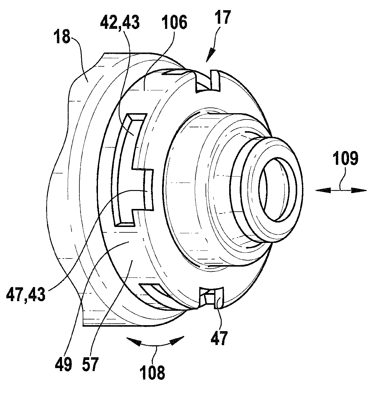
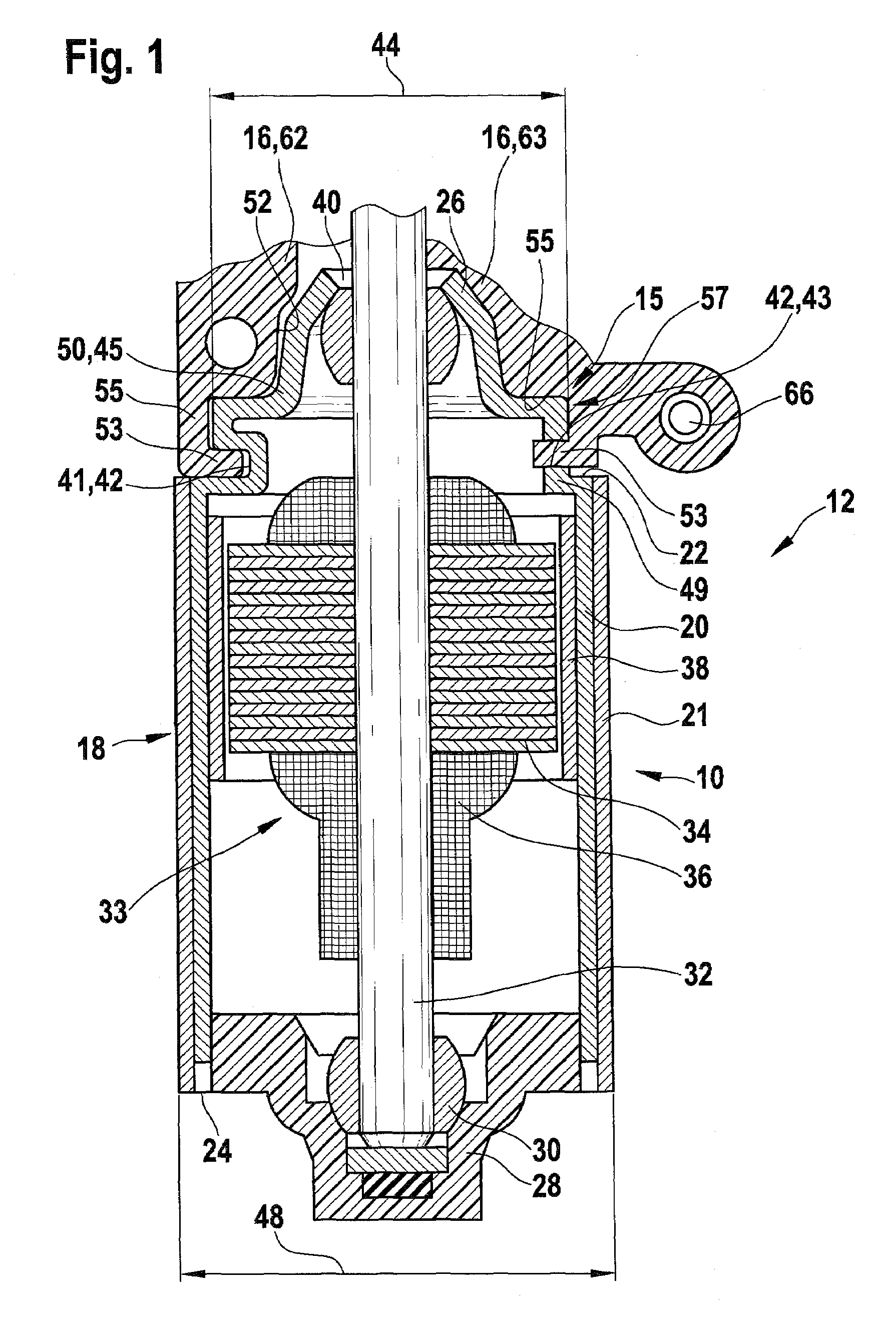
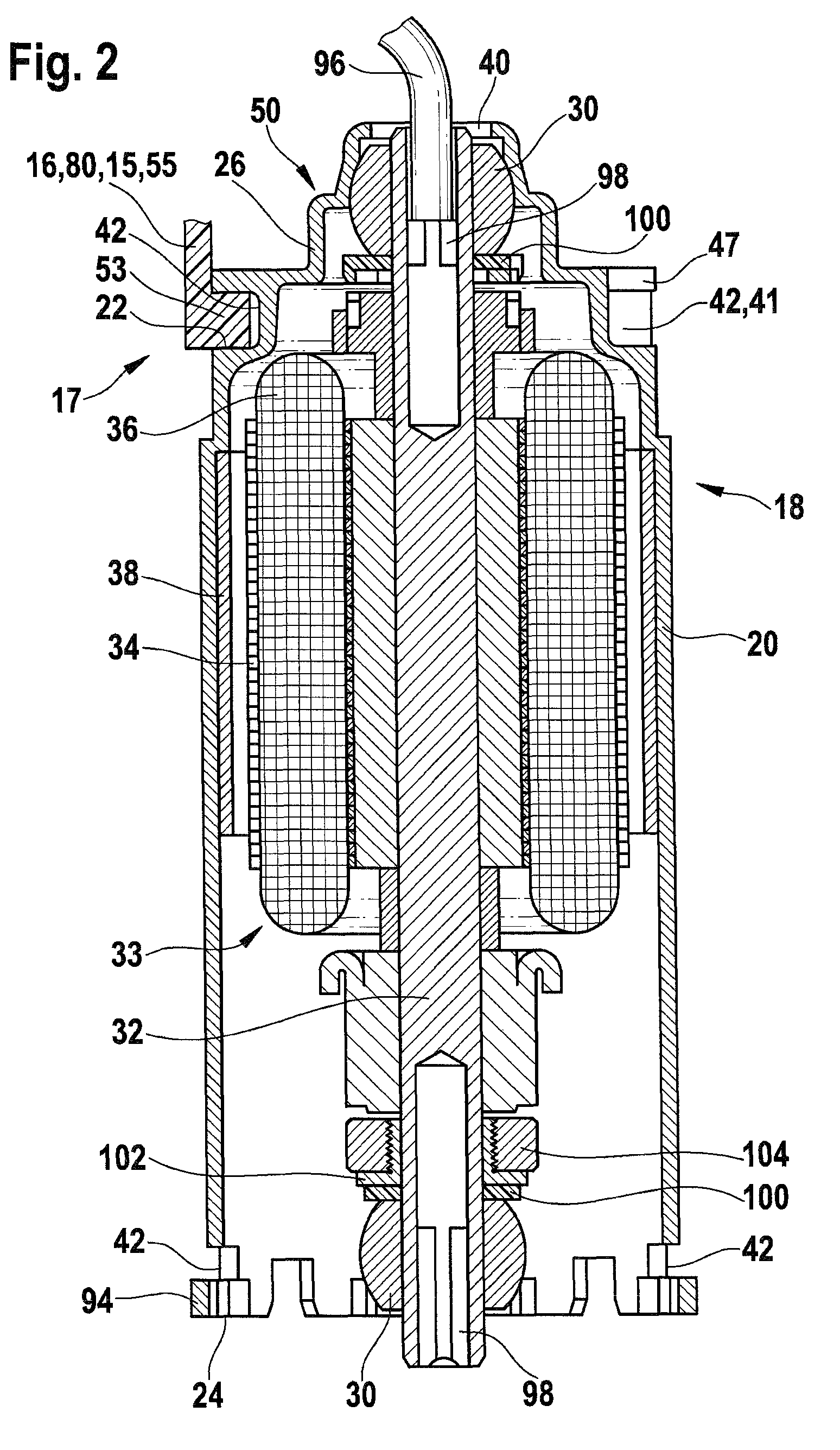
[0028]A transmission drive unit 12 is shown in FIG. 1, with which a separate electric motor 10 is connected with a partially-shown transmission interface 15 that is designed as transmission housing 16. Electric motor 10 includes a pole housing 18 with a pole housing jacket 20 and bearing covers 26, 28 integrally formed with its end faces 22, 24. Bearing covers 26, 28 accommodate bearings 30—which are designed as sliding bearings and, in particular, as calotte bearings in the exemplary embodiment—in which an armature 33 is supported via an armature shaft 32. An armature stack 34 with electrical windings 36 is located on armature shaft 32. Electrical windings 36 interact with permanent magnets 38 located on pole housing jacket 20. Armature shaft 32 passes through bearing cover 26 on end face 22 via a hole 40 located therein in the axial direction. Armature shaft 32 extends—with a not-shown driven element—into transmission element 16, in order to provide a drive torque for movable part...


PUM

PropertyMeasurementUnit
outer diameteraaaaaaaaaa
couple forceaaaaaaaaaa
weightaaaaaaaaaa

Abstract

An electric motor for actuators in a motor vehicle has an armature shaft, which is supported in a pole housing that includes a jacket and a bearing cover on at least on one end face for accommodating a bearing for the armature shaft, and at least one radial recess is formed in the pole housing, which, once the pole housing has been fully assembled, is suitable for engagement by at least one radial fastening segment of a transmission interface in the pole housing, in order to attach the electric motor to the transmission interface.

Description

CROSS-REFERENCE TO RELATED APPLICATION[0001]The invention described and claimed hereinbelow is also described in German Patent Application DE 10 2005 030 217.3 filed on Jun 29, 2005. This German Patent Application provides the basis for a claim of priority of invention under 35 U.S.C. 119(a)-(d).BACKGROUND OF THE INVENTION[0002]The present invention relates to an electric motor and a transmission drive unit for use in adjustment devices in a motor vehicle.[0003]Publication DE 100 19 512 A1 makes known a power window drive, the housing of which includes a pole pot and a housing that closes the pole pot. The housing that closes the pole pot is a transmission housing with an integrated electronics housing. A separate component—as a brush holder—is located between the two housing parts, and also serves as a seal between the two housing parts. The pole pot is composed of a deep-drawn, flattened cylindrical tube, on the open end of which a flange is integrally formed, in which holes are f...

Claims


Application Information

Patent Timeline
Patent Type & Authority Patents(United States)
IPC IPC(8): H02K5/00H02K5/16H02K5/04H02K5/26H02K7/14H02K7/116
CPCH02K7/1166Y10T29/49947Y10T74/2186H02K7/116
Inventor OBERLE, HANS-JUERGENSCHEER, DIETERSCHWENDEMANN, FRANZBERNAUER, CHRISTOF
Owner ROBERT BOSCH GMBH
Why Eureka
Try Eureka