Torque control circuit for impact tool

a technology of torque control circuit and impact tool, which is applied in the direction of electric variable regulation, process and machine control, instruments, etc., can solve the problems of high speed rotation fast consumption of electric power, and achieve the reduction of battery capacity, torque setting range, and output voltage

Inactive Publication Date: 2010-11-23
MOBILETRON ELECTRONICS
View PDF13 Cites 17 Cited by
  • Summary
  • Abstract
  • Description
  • Claims
  • Application Information

AI Technical Summary

Benefits of technology

[0012]However, with sufficient supply of voltage, after impacting a bolt or a nut with a fixed force for several times, the impulse of the subsequent impacts has less degree of tightening on the bolt or nut. Thus, for the sake of saving power, the torque control circuit of the impact tool in accordance with the present invention has a design that at the time point when the current of the electric motor raises to a preset current level, the previously described maximum electric motor current setting circuit is employed to control the current and stays for a short and fixed period of time (a fixed period of time indicating a fixed number of impacts) to thereafter automatically stop whereby the desired torque can be obtained with a most power saving manner.
[0013]Further, different from a power screwdriver that, at the time when encountering resistance against the rotation, causes the electric motor to almost stop for a period of time, the impact tool induces repeated impact each time it is subjected to resistance, with the electric motor maintaining high speed rotation. The high speed rotation fast consumes electric power. Thus, after a period of time of operation, the voltage level of the battery gets lowered, causing the current flowing into the electric motor to reduce and the torque that works against the tightening resistance reducing, meaning the force of each impact reducing. Under this condition, to ensure a wider range of torque control, the torque control circuit of the impact tool in accordance with the present invention elongates the time period of impact to provide an increased tightening force after the current of the electric motor reaches a preset level so as to widen the torque control range and thus obtaining stable output of torque. The torque control circuit of the impact tool of the present invention exhibits a design that effects torque control in response to the parameters of power supply voltage.
[0016]A major cause is that under the load of impact block, the power supply voltage for the electric motor has a significant difference in efficiency between high and low levels of voltage. When a high voltage is supplied, the electric motor has a high rotational speed and the high speed rotation, although increasing the frictional force of the impact block, increases the horizontal impact speed (V) that the impact block is released, making the impulse (P=MV) increased and thus increasing the output torque. When a low voltage is supplied, the rotational speed of the motor is low and the resistance of the impact block is low. The impact stroke can be done with the current being small. Thus, the maximum impulse of each impact is low and the overall maximum output torque cannot be made great. To allow the impact tool to operate for a long period of time with a fixed torque and fixed torque control range, the number of serially connected batteries can be increased to five. In this way, the lowest voltage level can be raised to around 14.0V, but a high voltage of 20V may be reached. Using the 20V high voltage to drive an electric motor that is of an operating voltage of around 14.4V may lead to the risks of over-heating and burning.
[0017]The torque control circuit of the impact tool in accordance with the present invention uses a maximum electric motor current setting circuit, together with a control circuit, to instruct a semiconductor power device to cut off an electric motor driving circuit, which is realized with pulse width modulation (PWM) techniques, such as the previously described integrated circuit having built therein a look-up table of various voltages and various currents corresponding to output torques. What is supplemented here is that the built-in look-up table may also provide outputs of voltages and torques corresponding to the PWM work loads. Thus, with the electric power of the batteries being sufficiently supplied to provide a high voltage or adding an additional battery to raise voltage for enhancing the torque setting range, the motor is not operated in an all period ON condition and is instead subjected to the control of ON / OFF operation of PWM so that the operation efficiency of the electric motor under high voltage is maintained high and average wattage is controlled by circuits featuring PWM and a maximum electric motor current setting circuit to eliminate the risk of over-heating.
[0018]Further, the motor temperature also causes influence of the efficiency. Thus, the torque control circuit of the impact tool in accordance with the present invention also considers temperature as an influencing factor and includes the influence caused by temperature in the look-up table built in the integrated circuit. The integrated circuit reads detected temperature from an electric motor operating temperature detection circuit and carries out analysis and determination. Thus, in total, multiple factors, including the battery voltage, PWM, and variation of operating temperature, are considered and this makes the control of torque very complicated. However, this can be done with a digital look-up table pre-established in the integrated circuit and the torque control of the impact tool can be eased.

Problems solved by technology

Further, different from a power screwdriver that, at the time when encountering resistance against the rotation, causes the electric motor to almost stop for a period of time, the impact tool induces repeated impact each time it is subjected to resistance, with the electric motor maintaining high speed rotation.
The high speed rotation fast consumes electric power.

Method used


Image

  • Torque control circuit for impact tool
  • Torque control circuit for impact tool
  • Torque control circuit for impact tool

Examples


Embodiment Construction

[0023]The following descriptions are of exemplary embodiments only, and are not intended to limit the scope, applicability or configuration of the invention in any way. Rather, the following description provides a convenient illustration for implementing exemplary embodiments of the invention. Various changes to the described embodiments may be made in the function and arrangement of the elements described without departing from the scope of the invention as set forth in the appended claims.

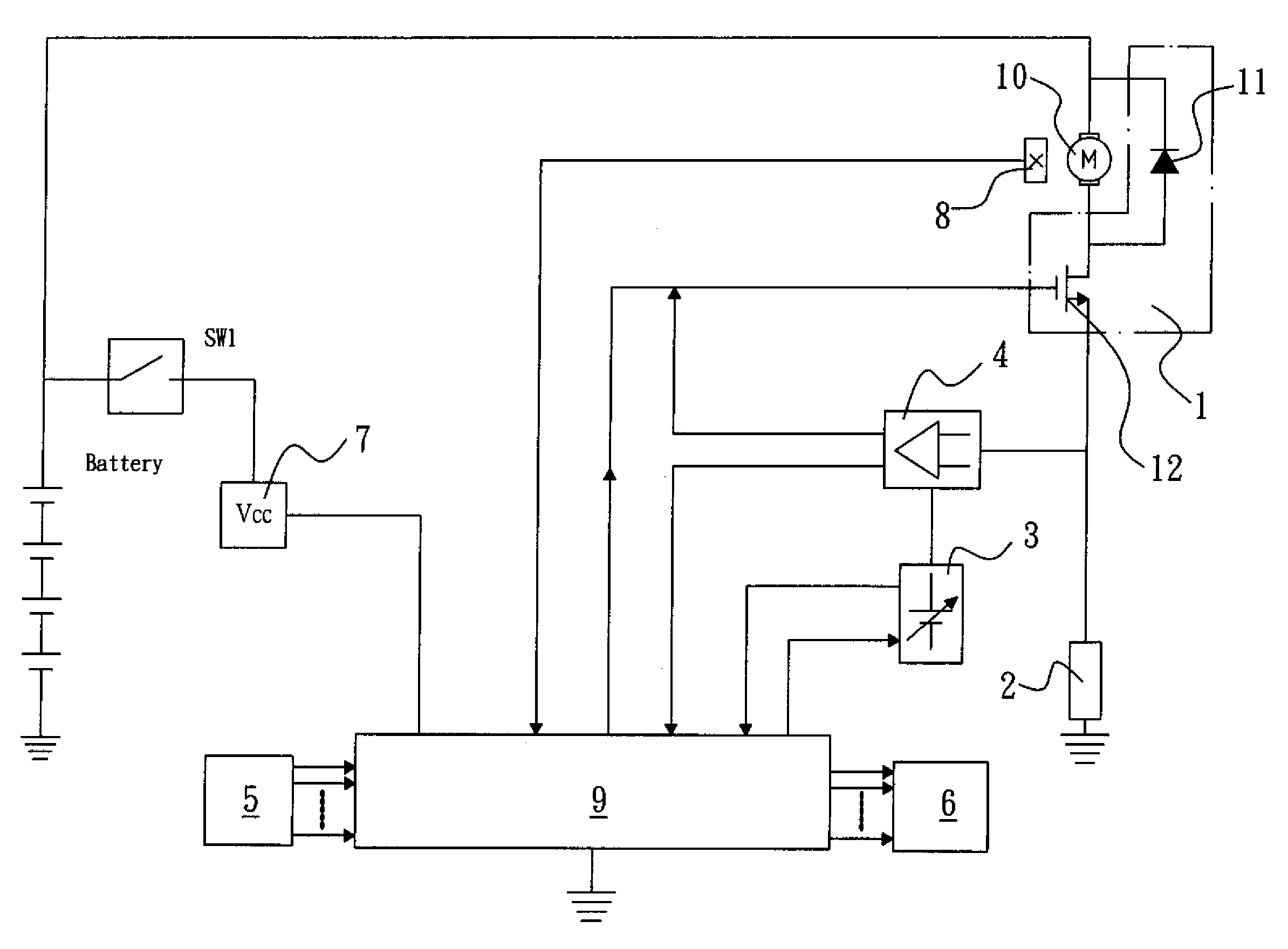
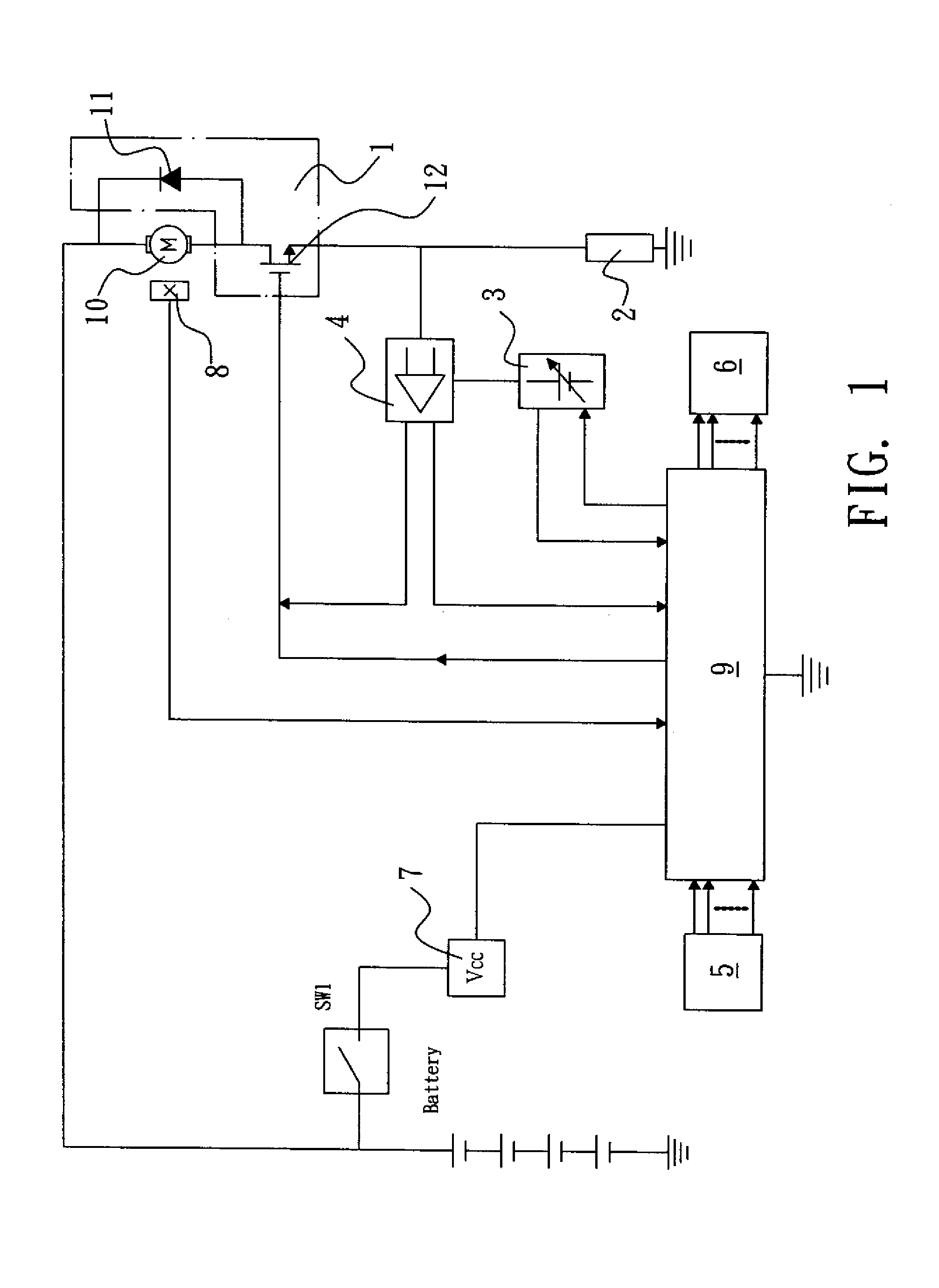
[0024]FIG. 1 is a block diagram illustrating the construction and signal transmission of a torque control circuit for impact tool in accordance with the present invention. As shown in the drawing, the torque control and battery discharge protection circuit for impact tool in accordance with the present invention is generally comprised of an electric motor driving circuit 1, an electric motor operating current detection circuit 2, a reference voltage generation circuit 3, a maximum electric motor ...


PUM


Abstract

A torque control circuit includes a motor driving circuit, a motor operating current detection circuit, a reference voltage generation circuit, a maximum motor current setting circuit, a torque setting circuit, an information output circuit, a regulated-voltage power supply circuit, a motor operating temperature detection circuit, and a control circuit. The control circuit includes an integrated circuit to carry out functions of reading information detection sources, processing, and instruction for execution of torque control and output terminals of the reference voltage generation circuit, the maximum motor current setting circuit, the motor operating temperature detection circuit, and the motor impedance torque setting circuit are respectively connected to corresponding input terminals of the integrated circuit to carry out desired control of torque supplied to the impact tool.

Description

BACKGROUND OF THE INVENTION[0001](a) Technical Field of the Invention[0002]The present invention relates to a torque control circuit of an impact tool, which provides a torque control technique that, at the time when the impact tool is operated to hit and tighten a bolt, realizes constant current control and employs an integrated circuit to effect precise control of output impact torque in response to the variation of temperature and voltage.[0003](b) Description of the Prior Art[0004]An impact tool is used to effect successive impact for tightening a tightened object. Using a sensor to detect the tightened degree of the tightened object at the moment just after an impact in order to effect control of torque is very difficult. Conventionally, displacement sensors are used for such detection, but the result is imprecise and the construction is complicated. Thus, commercialized products were hardly seen heretofore.[0005]With the advance of the power tools, rechargeable impact tools ar...

Claims


Application Information

Patent Timeline
Patent Type & Authority Patents(United States)
IPC IPC(8): G05B1/00
CPCH02P7/295
Inventor WEI, CHEN-KU
Owner MOBILETRON ELECTRONICS
Why Eureka
Try Eureka