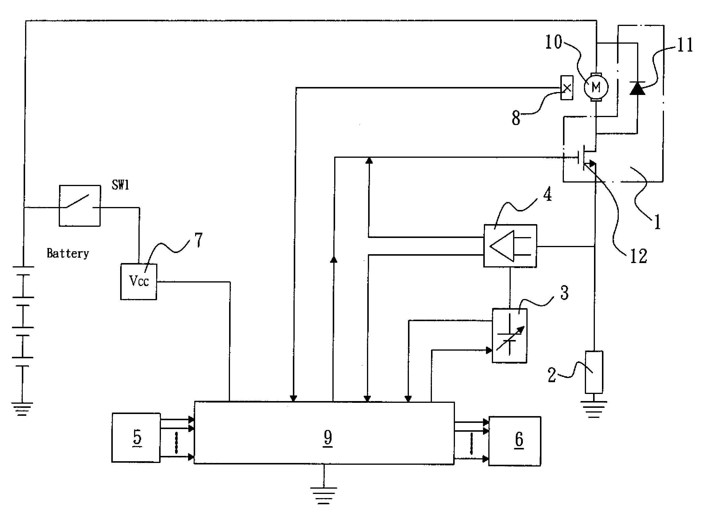
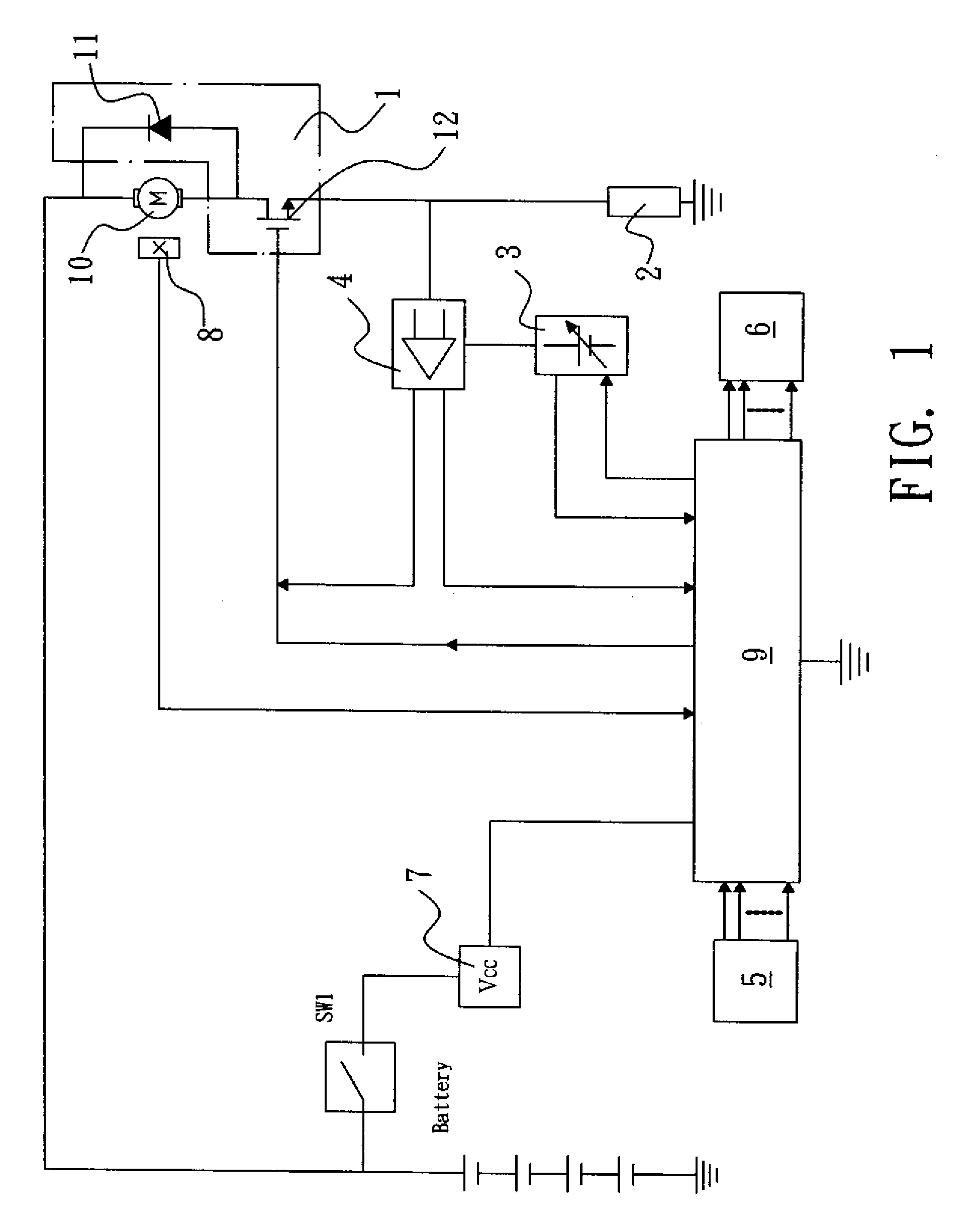
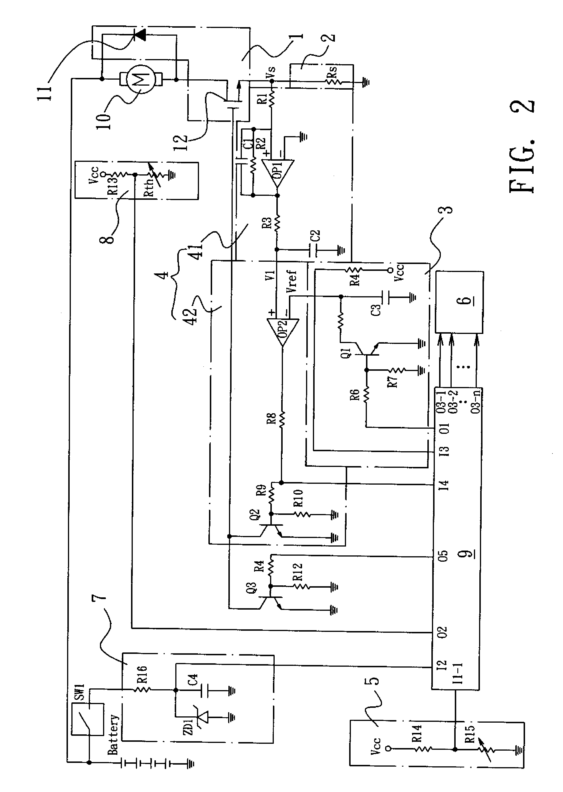
[0012]However, with sufficient supply of voltage, after impacting a bolt or a nut with a fixed force for several times, the impulse of the subsequent impacts has less degree of tightening on the bolt or nut. Thus, for the sake of saving power, the torque control circuit of the impact tool in accordance with the present invention has a design that at the time point when the current of the
electric motor raises to a preset current level, the previously described maximum electric motor current setting circuit is employed to control the current and stays for a short and fixed period of time (a fixed period of time indicating a fixed number of impacts) to thereafter automatically stop whereby the desired torque can be obtained with a most
power saving manner.
[0013]Further, different from a power screwdriver that, at the time when encountering resistance against the rotation, causes the electric motor to almost stop for a period of time, the impact tool induces repeated impact each time it is subjected to resistance, with the electric motor maintaining high speed rotation. The high speed rotation fast consumes
electric power. Thus, after a period of time of operation, the voltage level of the battery gets lowered, causing the current flowing into the electric motor to reduce and the torque that works against the tightening resistance reducing, meaning the force of each impact reducing. Under this condition, to ensure a wider range of torque control, the torque control circuit of the impact tool in accordance with the present invention elongates the time period of impact to provide an increased tightening force after the current of the electric motor reaches a preset level so as to widen the torque control range and thus obtaining stable output of torque. The torque control circuit of the impact tool of the present invention exhibits a design that effects torque control in response to the parameters of
power supply voltage.
[0016]A major cause is that under the load of impact block, the
power supply voltage for the electric motor has a
significant difference in efficiency between high and low levels of voltage. When a
high voltage is supplied, the electric motor has a high rotational speed and the high speed rotation, although increasing the frictional force of the impact block, increases the horizontal impact speed (V) that the impact block is released, making the impulse (P=MV) increased and thus increasing the output torque. When a
low voltage is supplied, the rotational speed of the motor is low and the resistance of the impact block is low. The impact
stroke can be done with the current being small. Thus, the maximum impulse of each impact is low and the overall maximum output torque cannot be made great. To allow the impact tool to operate for a long period of time with a fixed torque and fixed torque control range, the number of serially connected batteries can be increased to five. In this way, the lowest voltage level can be raised to around 14.0V, but a
high voltage of 20V may be reached. Using the 20V
high voltage to drive an electric motor that is of an
operating voltage of around 14.4V may lead to the risks of over-heating and burning.
[0017]The torque control circuit of the impact tool in accordance with the present invention uses a maximum electric motor current setting circuit, together with a control circuit, to instruct a
semiconductor power device to
cut off an electric motor
driving circuit, which is realized with
pulse width modulation (PWM) techniques, such as the previously described integrated circuit having built therein a look-up table of various voltages and various currents corresponding to output torques. What is supplemented here is that the built-in look-up table may also provide outputs of voltages and torques corresponding to the PWM work loads. Thus, with the
electric power of the batteries being sufficiently supplied to provide a high voltage or adding an additional battery to raise voltage for enhancing the torque setting range, the motor is not operated in an all period ON condition and is instead subjected to the control of ON / OFF operation of PWM so that the operation efficiency of the electric motor under high voltage is maintained high and average wattage is controlled by circuits featuring PWM and a maximum electric motor current setting circuit to eliminate the risk of over-heating.
[0018]Further, the motor temperature also causes influence of the efficiency. Thus, the torque control circuit of the impact tool in accordance with the present invention also considers temperature as an influencing factor and includes the influence caused by temperature in the look-up table built in the integrated circuit. The integrated circuit reads detected temperature from an electric motor
operating temperature detection circuit and carries out analysis and determination. Thus, in total,
multiple factors, including the
battery voltage, PWM, and variation of operating temperature, are considered and this makes the control of torque very complicated. However, this can be done with a digital look-up table pre-established in the integrated circuit and the torque control of the impact tool can be eased.


