
Method and apparatus for encoding or decoding two digital video signals arranged in a single-video signal path

a digital video and signal path technology, applied in the field of methods and apparatuses for encoding or decoding two digital video signals arranged in a singlevideo signal path, can solve the problems of affecting the signal quality, g. the s/n ratio, and every additional meter of cable, and achieve the effect of reducing the loss of amplitude resolution

Inactive Publication Date: 2010-11-23
GVBB HLDG R L
View PDF9 Cites 3 Cited by
  • Summary
  • Abstract
  • Description
  • Claims
  • Application Information

AI Technical Summary

Benefits of technology

[0010]A one-dimensional adaptive dynamic range compression (ADRC) is used to reduce the data word length of the two video signals to be transmitted via the SDI or HDSDI connection. To one of the two video signals (e.g. the teleprompter signal) a smaller data word length can be assigned than to the data word length of the other one (e.g. the playback signal), whereby the MSB bit (most significant bit) of the SDI connection is not used for carrying bits of the two compressed video signals. As an alternative, two compressed video signals having equal word length can be used whereby one video signal occupies the full range of 32 amplitude levels and the other video signal occupies a range of 31 amplitude levels.
[0016]it uses very little resources, i.e. it is a low-cost compression;

Problems solved by technology

However, a disadvantage is that the maximum distance between camera and base unit is restricted to about 100 meters, that the signals on the receiving side need to be equalized and that every additional meter of cable has a negative influence on the signal quality, e.g. the S / N ratio.

Method used


Image

  • Method and apparatus for encoding or decoding two digital video signals arranged in a single-video signal path
  • Method and apparatus for encoding or decoding two digital video signals arranged in a single-video signal path
  • Method and apparatus for encoding or decoding two digital video signals arranged in a single-video signal path

Examples


Embodiment Construction

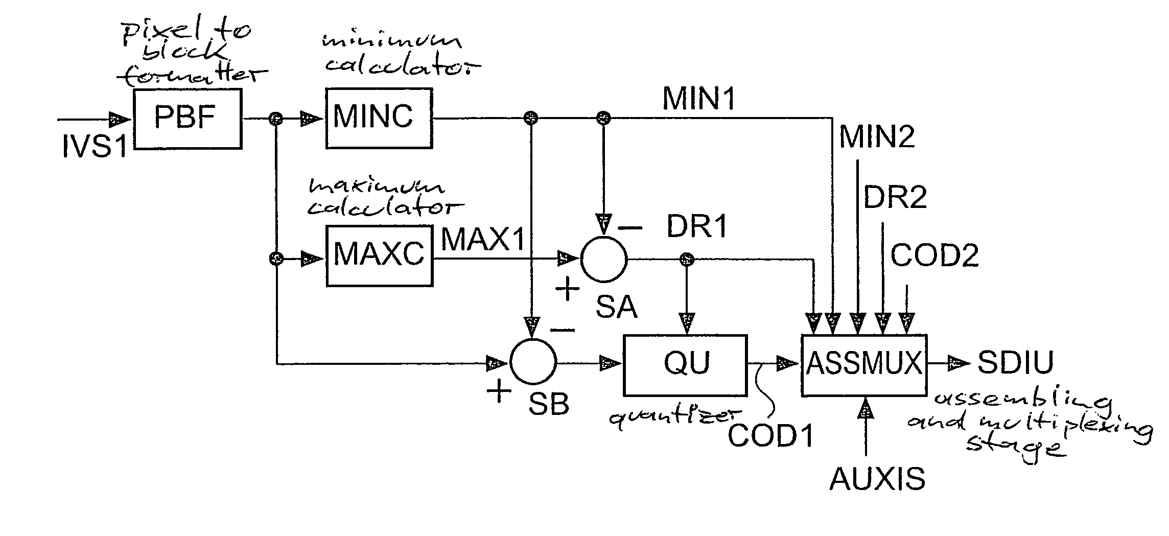
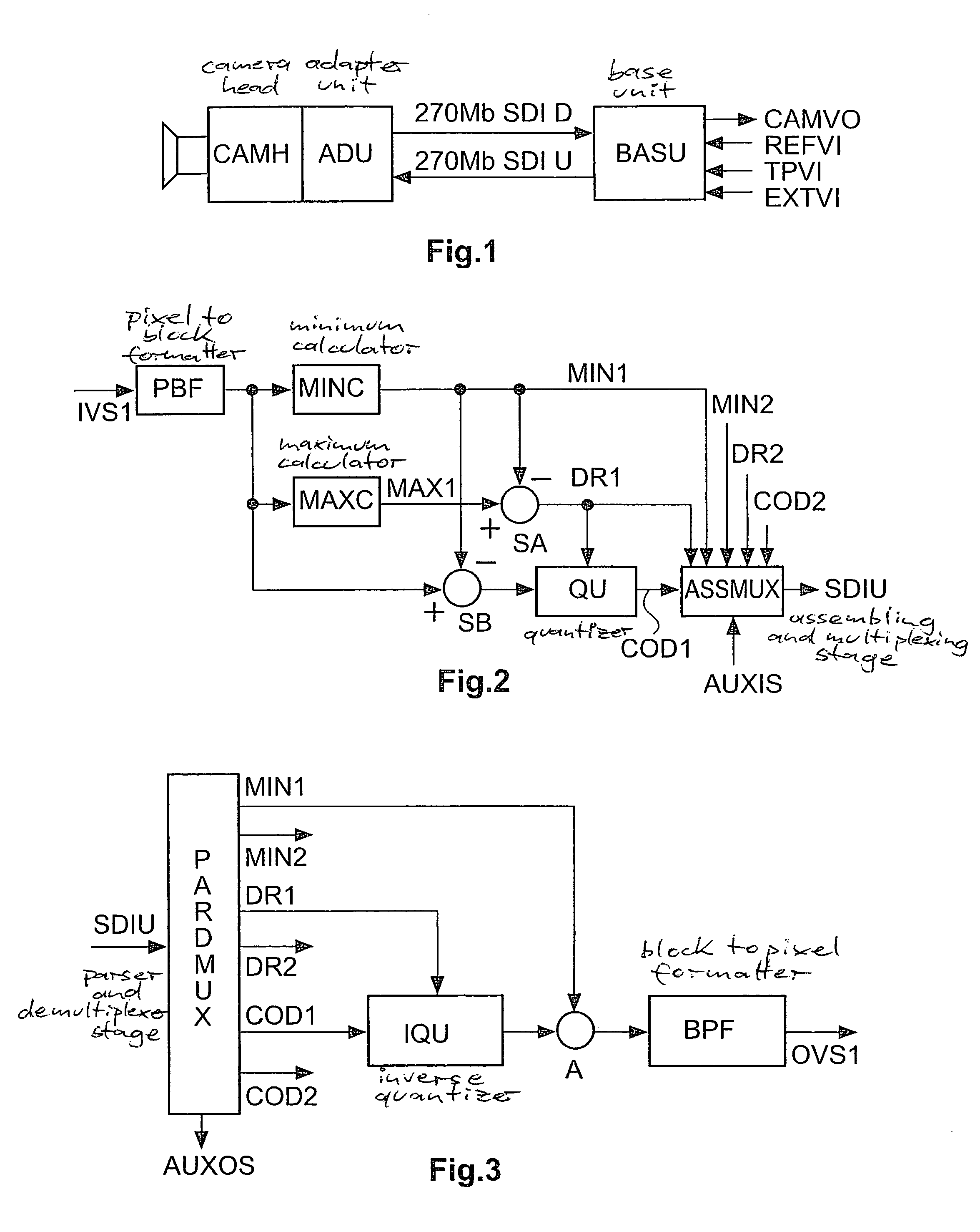
[0060]In FIG. 1 an adapter unit ADU is attached to a camera head CAMH. A base unit BASU receives a reference video input signal REFVI, a teleprompter video input signal TPVI and has an Extern video in terminal EXTVI for entering auxiliary signals. BASU outputs a camera video output signal CAMVO. The base unit sends to the adapter unit the above-described SDI / HDSDI upstream data stream SDIU carrying TP and Play-back, and receives from the adapter unit an SDI / HDSDI down-stream SDID carrying the camera video signal.

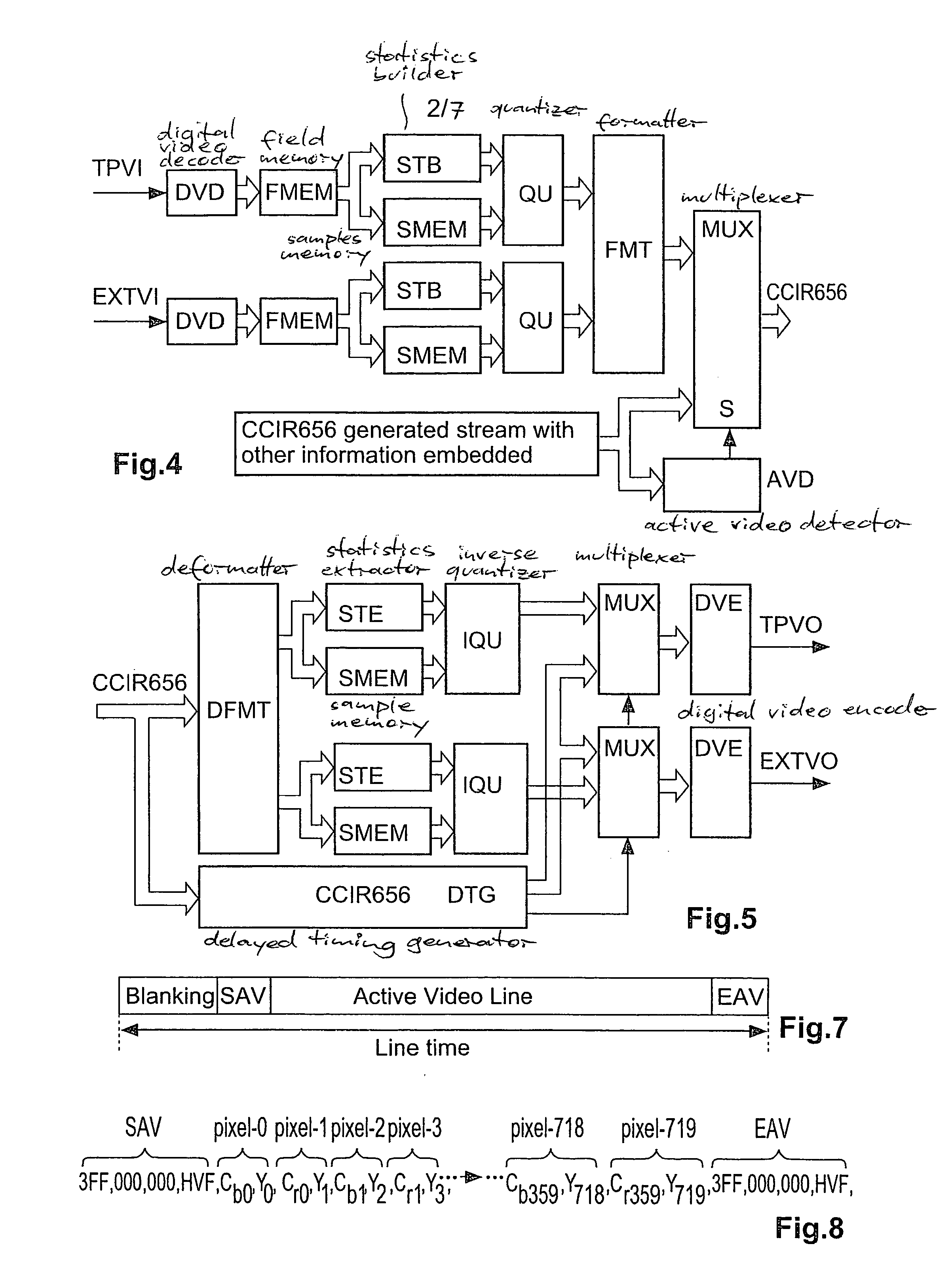
[0061]In FIG. 2 the encoder receives a digital video input signal IVS1. In the PAL, SECAM and NTSC TV systems the active video portion of one video line has 720 pixels with 1440 components. These components are arranged in a multiplexed fashion: Cb-Y-Cr-Y-Cb-Y-Cr-Y- etc., wherein Y represents an e.g. 10-bit luminance sample, Cb represents an e.g. 10-bit blue-component chrominance sample and Cr represents a corresponding red-component chrominance sample. The possible amplitud...


PUM


Abstract

In high-end professional video cameras, a triax system transfers various signals back and forth over a single coaxial cable between the camera and a base unit using frequency multiplexing. Current low-cost camera systems transfer several signals as analogue signals over separate wires or cables. However, a standard serial SDI signal from the camera to a base unit replaces the analogue camera CVBS video output signal achieving a maximum data rate of 270 Mbit / s. To improve efficiency, a single SDI or HDSDI connection transmits a digital playback video signal as well as a digital teleprompter video signal from the base unit to the camera. A one-dimensional adaptive dynamic range compression reduces the data word length of the two video signals transmitted via the SDI / HDSDI connection. A smaller data word length is assigned to one of the two video signals than to the data word length of the other one.

Description

CROSS REFERENCE TO RELATED APPLICATIONS[0001]This application claims the benefit of the EP Application No. 04292882.0 filed on Dec. 6, 2005 and 05090251.9 filed on Sep. 1, 2005, the disclosure of which is herewith incorporated by reference in its entirety.FIELD OF THE INVENTION[0002]The invention relates to a method and to an apparatus for encoding or decoding two digital video signals arranged in a single-video signal path, e.g. an SDI or HDSDI format video signal path.BACKGROUND OF THE INVENTION[0003]In the upper part of the market of professional video cameras a triax system is used for transferring various signals back and forth over a coaxial cable between the camera and a base unit. Transferring multiple signals in different direction over a single cable is feasible because frequency multiplexing is used in which to every type of signal a separate frequency band is assigned.[0004]In the lower part of the market a multi-core adapter solution is currently being used.[0005]In ear...

Claims


Application Information

Patent Timeline
Patent Type & Authority Patents(United States)
IPC IPC(8): H04N11/04G06K9/36
CPCH04N19/98
Inventor KUPPENS, CHRISROTTE, JEROENVAN ROOY, JAN
Owner GVBB HLDG R L
Learn More