
Audio message transfer sheet and manufacturing method thereof, and power supply circuit

a technology of power supply circuit and transfer sheet, which is applied in the direction of cell components, cell component details, instruments, etc., can solve the problems of address information, inability to print with the incorporated audio apparatus, and the thickness of the area to which the audio apparatus is pasted

Inactive Publication Date: 2010-11-23
TOPPAN MOORE CO LTD
View PDF38 Cites 6 Cited by
  • Summary
  • Abstract
  • Description
  • Claims
  • Application Information

AI Technical Summary

Benefits of technology

[0047]Furthermore, it is another object of the present invention to provide an audio information output sheet which can be downsized while securing a predetermined sound volume.
[0080]Furthermore, when the paper battery is mounted on the circuit substrate, if no connection terminal is formed in part of the area facing the positive electrode and negative electrode of the circuit substrate, part of the area facing the positive electrode and negative electrode of the circuit substrate is melted through ultrasonic vibration and the bonding force between the paper battery and circuit substrate is thereby increased.

Problems solved by technology

However, when the article to be delivered with printed information of which the sender wants to notify the destination is sent by the sender, the information printed on the article delivered from the sender is browsed at the destination, and thereby the information of which the sender wants to notify the destination is transferred to the destination, a desired message of the sender of the article to be delivered can be transferred to the destination only visually and in this way the type of transferable information is limited.
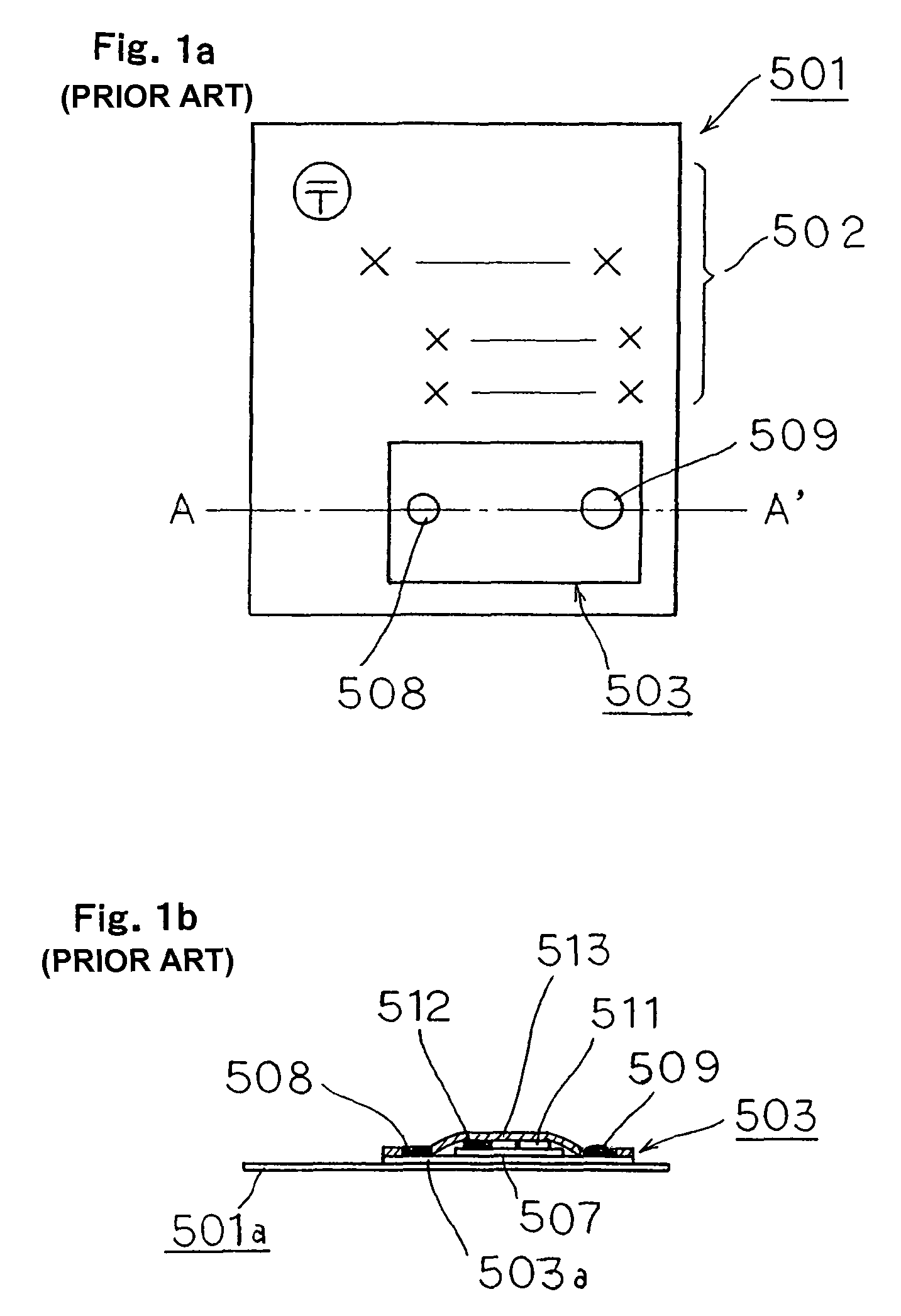
However, since the information carrier incorporating the above described audio apparatus is constructed of an audio apparatus mounted on or pasted to the direct mail component on which address information, etc., is printed, there is a problem that the area to which the audio apparatus is pasted becomes so thick that the address information, etc., cannot be printed with the audio apparatus incorporated.
Furthermore, since the audio apparatus is mounted on or pasted to the direct mail component and the area is thick, if the direct mail is folded or an external force is applied to this area, the audio apparatus may be peeled from the direct mail component.
When the direct mail is two-folded or folded in a Z-figure, the direct mail should be folded in such a way as to avoid the area where the audio apparatus is mounted, which causes a problem that the area where the audio apparatus is mounted or the area which becomes a folding line when the direct mail is folded is limited.
Furthermore, the above described audio information output sheet capable of recording / reproducing audio information needs to be provided with audio information outputting means such as a speaker for outputting the recorded audio information, but the audio information outputting means such as a speaker is required to have certain dimensions to secure a predetermined sound volume, which results in a problem that it is difficult to reduce the size of the entire audio information output sheet.
However, in a conventional POP indicator, only advertisement information on goods is displayed as a POP, and therefore visitors to the store can only visually recognize advertisement information and there are cases where depending on the design of the POP or size of characters, etc., such a POP indicator may not be adequate to attract attention.
Furthermore, in the case of the POP indicator, an amount of information of advertisement information displayed as a POP is limited by the size thereof and the POP indicator is often attached to a showcase and in that case, the size of the POP indicator is preferably not too large so that it is kept out of the way of a visitor when the visitor picks up a product from the showcase, and therefore there is a problem that it is difficult to display a large amount of advertisement information as a POP.
However, such a recording / reproducing instrument can be used only when sending an article to be delivered and there has been actually no recording / reproducing instrument that can be used to send a message with audio itself as a main article to be delivered.
However, as described above, in the case of the structure that the recording button is made easily detachable so that the recording button is detached after audio information is recorded to thereby avoid audio information from being erased by misoperation of the recording button, when an audio card with audio information recorded therein is delivered, the audio card is delivered to the destination with part of the audio card detached, causing a problem that the appearance of the audio card to be delivered becomes unattractive.
Furthermore, in the case of the structure that when the playback button and recording button are pressed simultaneously after audio information is recorded, further recording of audio information is prohibited, there is a problem that it is not possible to visually confirm whether the recording of audio information is prohibited or not.
As such, the double postal card combining the transmitting message card and reply message card has a limited amount of information that can be transferred from the sender to the receiver or from the receiver to the sender and both the transmitting message card and reply message card need to include the address information, which further limits the amount of information thereof.
However, though an amount of information that can be transferred may be increased with such a double postal card, the information can be transferred from the sender to the receiver or from the receiver to the sender only visually, which limits the type of information that can be transferred.
However, even with the above described double postal card with the structure that the recording button is easily detachable so that detaching the recording button after audio information is recorded prevents audio information from being erased by misoperation of the recording button, when this reply message card is sent with audio information recorded in the reply message card as described above, the reply message card is sent back to the sender with part thereof detached, which results in a problem that the appearance of the reply message card sent back becomes unattractive.
Such a problem is not limited to the above described double postal card, and can also occur with an audio information delivery component combining a transmitting message section and reply message section.
However, the above described label, to the surface of which convex form processing including Braille characters is applied, can transfer information expressed in Braille characters to the visually handicapped who can read Braille characters, but cannot transfer information to the visually handicapped who cannot read Braille characters.
For this reason, even if a label, to the surface of which convex form processing including Braille characters is applied is used, there still is a problem that it is difficult to transfer information to many visually handicapped and people with weak sight.
Moreover, doing so requires an additional operation, which results in reduced productivity and increased cost.
However, as described above, when part of the paper battery is folded and the positive electrode and negative electrode are thereby formed on the same surface, this means that the paper battery is continuously used with part of the paper battery folded and this involves a problem that the paper battery is used in an environment unfavorable to the paper battery compared to the use of the paper battery without folding.
However, as described above, when the paper battery and circuit substrate are connected using an anisotropic / conductive film or anisotropic / conductive adhesive and the paper battery is mounted on a circuit substrate to thereby manufacture a power supply circuit, the anisotropic / conductive film or anisotropic / conductive adhesive is applied to the electrodes of the paper battery first, and then the paper battery and circuit substrate are provisionally crimped and then the paper battery and circuit substrate are completely crimped, which results in a problem that such a manufacturing step is more complicated and productivity is reduced.
Furthermore, there is also a problem that the anisotropic / conductive film or anisotropic / conductive adhesive cannot be easily controlled, is expensive and thereby requires complicated control and increases the manufacture cost of the power supply circuit.

Method used


Image

  • Audio message transfer sheet and manufacturing method thereof, and power supply circuit
  • Audio message transfer sheet and manufacturing method thereof, and power supply circuit
  • Audio message transfer sheet and manufacturing method thereof, and power supply circuit

Examples


third embodiment

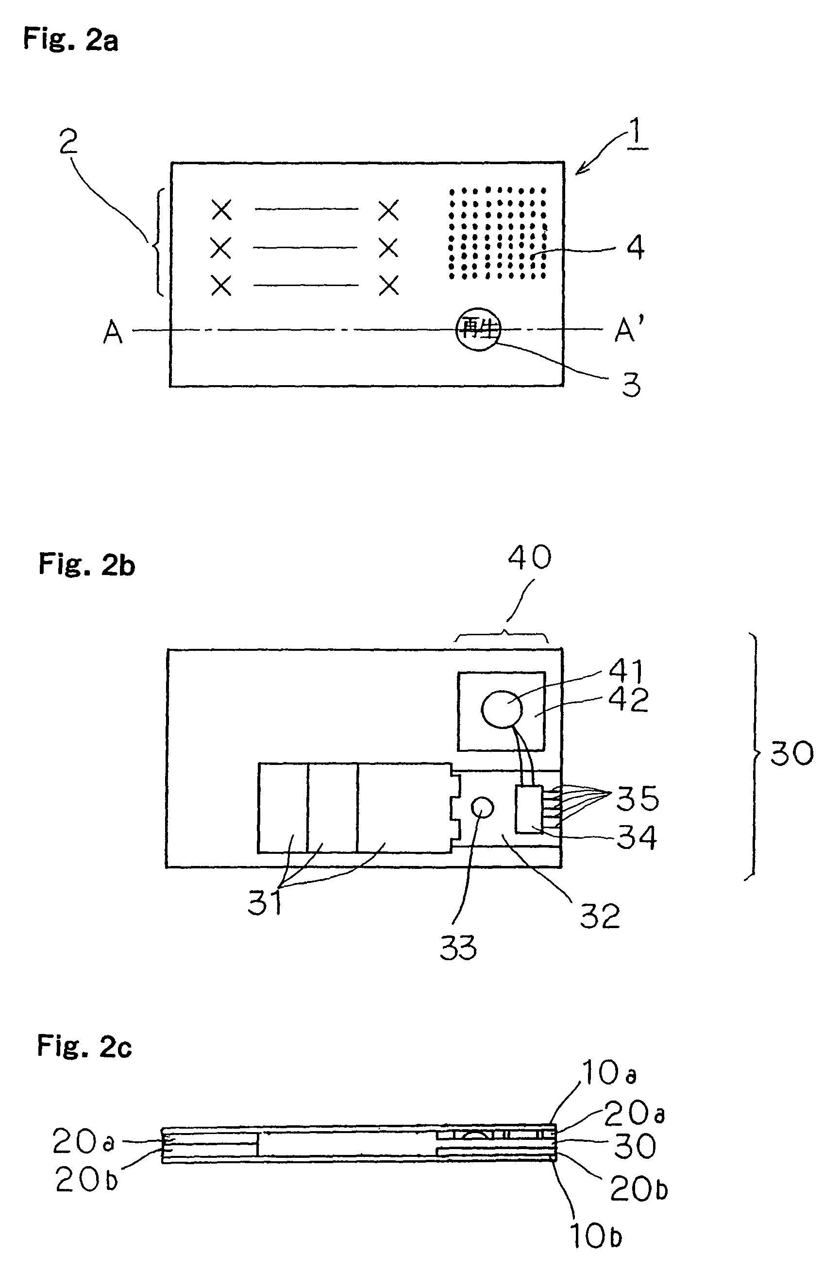
[0266]FIG. 9a is a plan view of an audio message transfer sheet according to a third embodiment of the present invention, FIG. 9b illustrates an inner structure of the audio message transfer sheet 201 shown in FIG. 9a and FIG. 9c is a cross-sectional view along the line A-A′ shown in FIG. 9a. Furthermore, FIG. 10 illustrates a recording area of the IC chip 234 shown in FIG. 9b.

[0267]As shown in FIGS. 9a, 9b, this embodiment is equivalent to the first embodiment further provided with three switches 233a to 233c to be pressed when audio information recorded in an IC chip 234 is reproduced on an audio substrate 32 and three playback buttons 203a to 203c printed in the areas facing the switches 233a to 233c on a surface sheet 10a. Furthermore, as shown in FIG. 10, the recording area of the IC chip 234 in which audio information is recorded is divided into three areas 234a to 234c and different pieces of audio information are recorded in the respective areas 234a to 234c.

[0268]In the a...

fourth embodiment

[0271]FIG. 11a is a plan view of an audio message transfer sheet according to a fourth embodiment of the present invention, FIG. 11b illustrates an inner structure of the audio message transfer sheet 301 shown in FIG. 11a and FIG. 11c is a cross-sectional view along the line A-A′ shown in FIG. 11a.

[0272]As shown in FIGS. 11a to 11c, this embodiment is equivalent to the first embodiment further provided with two audio information output sections 340a, 340b on an audio information recording / reproducing section 330, and a surface sheet 310a is provided with audio output areas 304a, 304b for outputting audio information from these audio information output sections 340a, 340b through bend lines 305a, 305b. Furthermore, support sheets 320a, 320b are divided into three portions so as to correspond to three adjoining areas along the bend lines 305a, 305b of the surface sheet 310a so that the audio output areas 304a, 304b can be folded along the bend lines 305a, 305b. An information display...

fifth embodiment

[0279]FIG. 12a is a plan view of an audio message transfer sheet according to a fifth embodiment of the present invention, FIG. 12b illustrates an inner structure of the audio message transfer sheet shown in FIG. 12a and FIG. 12c is a cross-sectional view along the line A-A′ shown in FIG. 12a.

[0280]As shown in FIGS. 12a to 12c, this embodiment only differs from the first embodiment in that the outside shapes of support sheets 420a, 420b are smaller than the outside shapes of the surface sheets 10a, 10b.

[0281]Thus, the present invention is equally applicable to a case where the outside shapes of the support sheets 420a, 420b are smaller than the outside shapes of the surface sheets 10a, 10b and a case where the outside shapes of the support sheets 420a, 420b are greater than the outside shapes of the surface sheets 10a, 10b.


PUM

PropertyMeasurementUnit
diameteraaaaaaaaaa
diameteraaaaaaaaaa
thicknessaaaaaaaaaa

Abstract

Sheet-like audio information recording / reproducing means capable of recording / reproducing audio information is sandwiched between two support sheets from front and back only in part of the area thereof and these two support sheets are further sandwiched between two surface sheets and the support sheets and surface sheets are bonded together.

Description

[0001]This Application is the National Phase of International Application No. PCT / JP2004 / 012465 filed Aug. 30, 2004, which designated the U.S. and was not published under PCT Article 21(2) in English, and this application claims, via the aforesaid International Application, the foreign priority benefit of and claims the priority from Japanese Application No. 2003-304719, filed Aug. 28, 2003, Japanese Application No. 2003-304720, filed Aug. 28, 2003, Japanese Application No. 2003-406656, filed Dec. 5, 2003, Japanese Application No. 2004-107536, filed Mar. 31, 2004, Japanese Application No. 2004-158298, filed May 27, 2004, Japanese Application No. 2004-158299, filed May 27, 2004, Japanese Application No. 2004-177021, filed Jun. 15, 2004, Japanese Application No. 2004-177023, filed Jun. 15, 2004, Japanese Application No. 2004-177024, filed Jun. 15, 2004, and Japanese Application No. 2004-177025, filed Jun. 15, 2004, the complete disclosures of which are incorporated herein by reference...

Claims


Application Information

Patent Timeline
Patent Type & Authority Patents(United States)
IPC IPC(8): H04R25/00H04B5/00H04R1/02H01L41/053H01L41/083B42D15/02H01M6/40H01M50/207H01M50/247
CPCB42D15/022H01M2/10H01M6/40H01M50/207H01M50/247G10K15/04G10L13/02H04R17/00B42D15/02
Inventor ISETANI, YUKIHIKOOKADA, TAKAAKISHIMIZU, HIDEOIDE, YOSHIAKIFUKUDA, YASUHIROYAMAKAMI, TAKESHIHANAZAWA, FUMIHIROYAMAZAKI, AKIRA
Owner TOPPAN MOORE CO LTD
Learn More