Optic film and backlight module using same

a backlight module and optical film technology, applied in the field of optical film, can solve the problems of high cost of backlight module, complicated manufacturing process, and high expense of optical film

Inactive Publication Date: 2010-02-25
MAI CHIEN CHIN +1
View PDF2 Cites 2 Cited by
  • Summary
  • Abstract
  • Description
  • Claims
  • Application Information

AI Technical Summary

Benefits of technology

[0010]The primary purpose of the present invention is to overcome the drawback of the conventional optic film that employs a complicated process and requires increased material expenses by using a diffusion layer formed by coating a resin in which diffusion beads are mixed and well stirred on an underside of a substrate to realize both diffusion and condensation of light.
[0012]Another objective of the present invention is to provide an optic film that comprises a substrate and a condensation layer. The substrate has a light incidence surface and a light emission surface. The light incidence surface and the light emission surface of the substrate are both treated by knurling or sand blasting to form a roughened frosted surface. With the light emission surface of the substrate being treated to form a roughened frosted surface, when the condensation layer is positioned on the light emission surface, the bonding force between the condensation layer and the substrate can be enhanced, and light is subjected to secondary diffusion by the frosted surface of the light emission surface before the light is condensed by the condensation layer and leaving the optic film.
[0014]Yet a further objective of the present invention is to provide a backlight module, in which the optic film described above is embodied. With the light incidence surface of the substrate being subjected to knurling or sand blasting to form a roughened frosted surface and further with a condensation layer arranged on the light emission surface of the substrate, since the condensation layer has prism-like micro-structures and since the light incidence surface of the substrate is treated by knurling or sand blasting to form the roughened frosted surface, when light enters the substrate through the light incidence surface, the light is diffused first and is then subjected to condensation by the condensation layer, whereby the optic film realizes both diffusion and condensation of light so that the number of optic films used in the backlight module can be reduced and excellent uniformity and brightness of light can be ensured for the light source of the backlight module.

Problems solved by technology

The optic films are often of high expenses and this makes the costs of the backlight module very high and also leads to troubles and problems associated with complicated inventory of pails.
This complicates the manufacturing process and also increases the material costs.

Method used


Image

  • Optic film and backlight module using same
  • Optic film and backlight module using same
  • Optic film and backlight module using same

Examples


Embodiment Construction

[0025]The following descriptions are of exemplary embodiments only, and are not intended to limit the scope, applicability or configuration of the invention in any way. Rather, the following description provides a convenient illustration for implementing exemplary embodiments of the invention. Various changes to the described embodiments may be made in the function and arrangement of the elements described without departing from the scope of the invention as set forth in the appended claims.

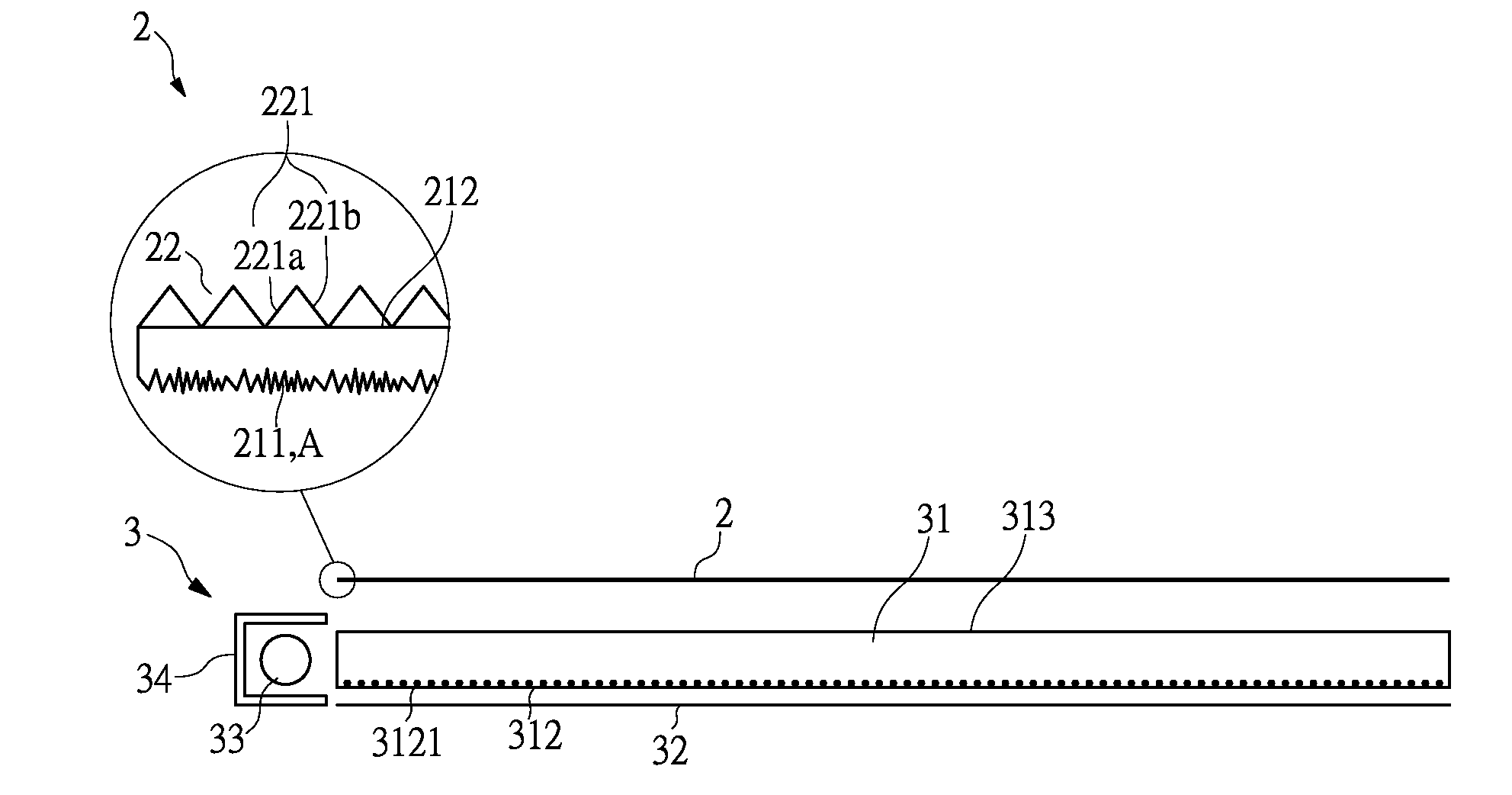
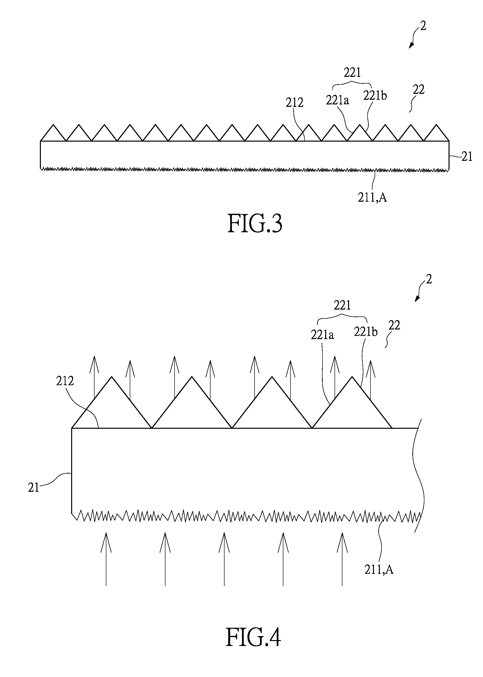
[0026]With reference to the drawings and in particular to FIG. 3, an optic film constructed in accordance with the present invention, generally designated with reference numeral 2, comprises a substrate 21 and a condensation layer 22.

[0027]The substrate 21 is made of a high-molecule material, such as polycarbonate (PC), polyethylene terephthalate (PET) and polymethyl methacrylate (PMMA). The substrate 21 has a light incidence surface 211 and a light emission surface 212, wherein the light inciden...


PUM


Abstract

An optic film includes a substrate and a condensation layer. The substrate has a light incidence surface and a light emission surface. The light incidence surface is treated to form a roughened frosted surface. The condensation layer is arranged on the light emission surface of the substrate and forms prism-like micro-structures. With the light incidence surface of the substrate being directly subjected to knurling or sand blasting to form the roughened frosted surface, when light enters the substrate through the light incidence surface, the light is diffused first by the frosted surface of the light incidence surface and is then subjected to condensation by the condensation layer, whereby when the optic film is applied to a backlight module, the optic film can effect both diffusion and condensation of light, so that the number of optic films used in the backlight module can be reduced.

Description

BACKGROUND OF THE INVENTION[0001](a) Technical Field of the Invention[0002]The present invention relates to an optic film, and in particular to a structure that features both diffusion and condensation of light.[0003](b) Description of the Prior Art[0004]A thin-film transistor liquid crystal display (TFT-LCD) comprises a light source that is provided by a backlight module. The backlight module must provide light of excellent uniformity and brightness in order to ensure excellent subsequent applications and uses.[0005]The backlight module uses various numbers of optic films, which include a diffusion film for diffusion of light and a prism film that condenses light. The number and arrangement of the optic film can be varied as desired. The optic films, either the diffusion film or the prism film, have only a single function with respect to the light transmitting therethrough. Thus, a great number of optic films must be simultaneously used in order to achieve desired optic results. Th...

Claims


Application Information

Patent Timeline
Patent Type & Authority Applications(United States)
IPC IPC(8): G02B5/02F21V8/00F21V3/04
CPCG02B6/0053G02B6/0051
Inventor MAI, CHIEN-CHINYIN, JUI-TANGWANG, YEONG-FENG
Owner MAI CHIEN CHIN
Why Eureka
Try Eureka