Exercise arm apparatus with pivotal linkage system

a technology of pivotal linkage and exercise arm, which is applied in the direction of sport apparatus, gymnastic exercise, weights, etc., can solve the problems of reduced exercise motion range, convenience and safety, and difficulty for users to maintain strict form, so as to reduce material requirements, reduce material costs, and improve the effect of performan

Inactive Publication Date: 2007-10-11
HOIST FITNESS SYST
View PDF5 Cites 10 Cited by
  • Summary
  • Abstract
  • Description
  • Claims
  • Application Information

AI Technical Summary

Benefits of technology

[0022] The two exercise arm assemblies are separately connected to the load and can be used independently of one another, or may be pulled together if desired. This arrangement distributes the load or resistance uniformly to each arm, preventing the user's dominant arm from doing more of the work during the exercise movement.
[0023] The apparatus is of relatively low cost to manufacture, due to its simplicity and reduced material requirements. In prior art arrangements where a large block of steel was required as a counterbalance, material expense is increased, and further machining is required to attach the block to the end of a pivot member or exercise arm. In contrast, in this apparatus, the same amount of work is required to mount the connecting link as would be needed if the connecting link were made of hollow tubing, as in the past, and no additional parts need to be attached in order to provide the required counter-weight. Solid metal bar does not cost as much as a large block of steel or extra weight plates. This arrangement also does not require a portion of the weight stack to be permanently pinned, thereby providing more available exercise weight.
[0024] In one embodiment, the connecting link travels in a substantially straight line, so that there is little or no resistance change or “camming over” effect to the counter-balance, as would occur with a leverage type counter-balance which travels in an arcuate path. As the position of such a counter-balance changes along the path, there is a slight variation in the counter-balancing effect which is felt by the user. With a spring counter-balance as used in some prior art devices, there is also a resistance change as the spring stretches. When the load bearing cable travels in a substantially straight line, there is little or no “drop off” in resistance felt by the user.

Problems solved by technology

The major disadvantage in these machines is that it is difficult for the user to maintain strict form when performing the exercise.
Also, this machine has a reduced range of exercise motion.
A further disadvantage is convenience and safety.
The disadvantages of the original pulldown machines brought about the development of the rigid arm pulldown machine.
However, because it does not have a free-swinging bar extending horizontally from hand-to-hand, it provides a safer, more restricted exercise movement with a greater range of travel.
One disadvantage to the rigid arm design is the weight of the exercise arm.
A weight attached directly to the rearward end of an exercise arm needs to increase in size and weight the closer it is placed to the pivot, or it will not offset the weight of the handle end of the arm.
If the counterweight is placed close to the pivot, it will be larger and more expensive.
This takes up more space and can pose a safety issue for anyone walking behind the machine.
Springs strong enough to offset the weight of the handle and allow for adequate handle travel can end up being fairly long and this will affect the design of the machine.
Springs do not maintain an even resistance throughout the length of their stretch, which could affect the resistance and smoothness of motion felt by the user.
Over time, springs tend to lose their tension, which would lessen their ability to counter-balance the exercise arm adequately.
Additionally, springs tend to fatigue and ultimately break after repeated use, resulting in machine “down time”, additional maintenance expense, and possible injury.
One disadvantage to such a system is that the amount of resistance available to a user is reduced.
This results either in less weight for the weight stack or requires a heavier weight stack, increasing the cost to manufacture the machine.
This uses a complicated linkage system and increases both the size of the machine and the cost to produce it.
In prior art arrangements where a large block of steel was required as a counterbalance, material expense is increased, and further machining is required to attach the block to the end of a pivot member or exercise arm.

Method used


Image

  • Exercise arm apparatus with pivotal linkage system
  • Exercise arm apparatus with pivotal linkage system
  • Exercise arm apparatus with pivotal linkage system

Examples


Embodiment Construction

[0048] Certain embodiments as disclosed herein provide for an exercise arm assembly for an exercise machine which can be used in various exercises.

[0049] After reading this description it will become apparent to one skilled in the art how to implement the invention in various alternative embodiments and alternative applications. However, although various embodiments of the present invention are described herein, it is understood that these embodiments are presented by way of example only, and not limitation. As such, this detailed description of various alternative embodiments should not be construed to limit the scope or breadth of the present invention as set forth in the appended claims.

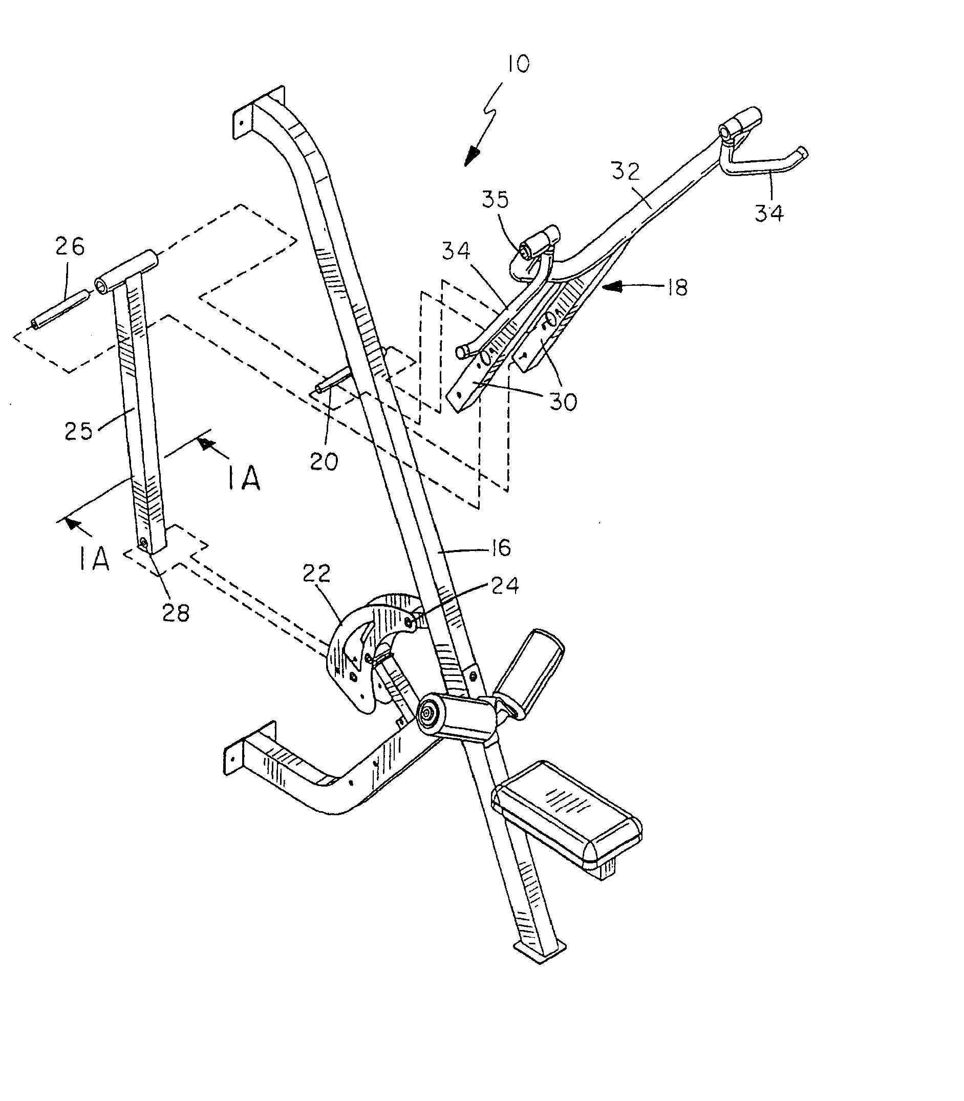
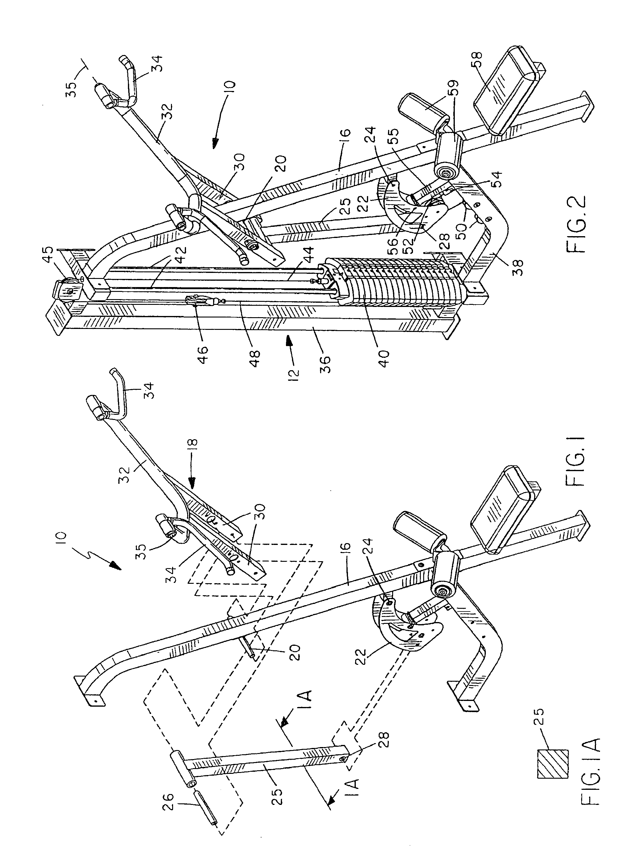
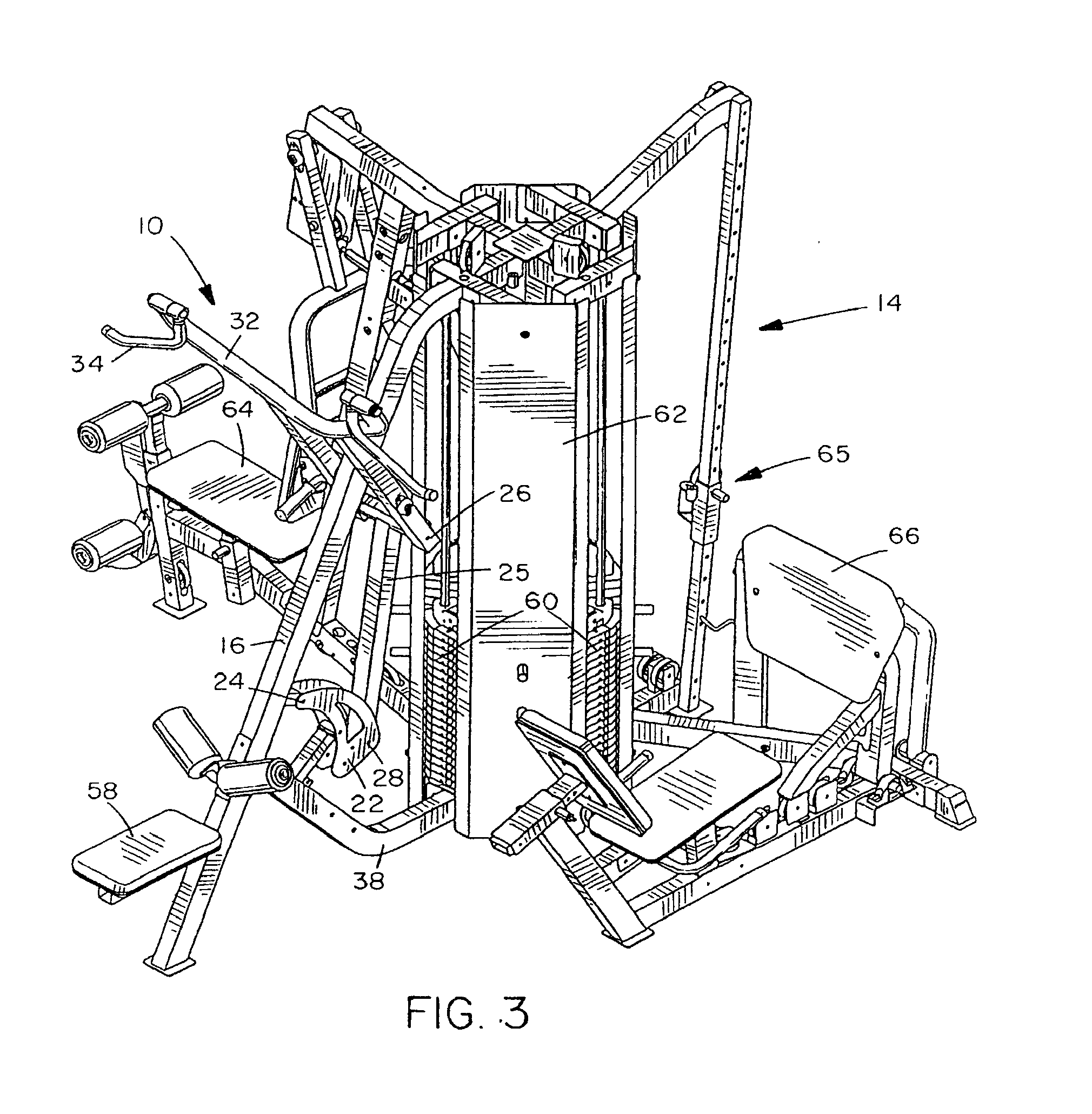
[0050]FIGS. 1 and 1A of the drawings illustrate an exercise arm apparatus 10 according to a first embodiment, while FIGS. 2, 4 and 5 illustrate the apparatus 10 mounted on a first exercise machine 12, and FIG. 3 illustrates the apparatus 10 mounted on a different, multi-station exercise machine ...


PUM


Abstract

An exercise arm apparatus has a stationary frame, a first pivoting arm pivoted to the frame at a location intermediate its ends for rotation about a first pivot axis, a second pivoting arm pivotally connected to the frame for rotation about a second pivot axis spaced from the first pivot axis, and a connecting link pivotally connected to the first arm and second arm. The first arm is an exercise arm with handles at one end for gripping by a user, and the connecting link is of sufficient weight to form a counter-weight to counter-balance the first exercise arm into a rest position corresponding to a start position for an exercise movement. In one example the connecting link is a solid, elongate bar of heavy metal or equivalent material.

Description

CROSS REFERENCE TO RELATED APPLICATIONS [0001] This application is a continuation of application Ser. No. 10 / 254,386 filed on Sep. 25, 2002, which was a Continuation-In-Part of application Ser. No. 09 / 772,812 filed Jan. 30, 2001, now U.S. Pat. No. 6,491,609, and the contents of each of these preceding applications are incorporated herein by reference in their entirety.Background [0002] 1. Field of the Invention [0003] The present invention relates generally to weight lifting exercise machines, and is particularly concerned with an exercise arm apparatus for such a machine having pivotal linkage system for linking the arm to an exercise resistance such as a weight stack, springs, or other load. [0004] 2. Related Art [0005] The pulldown exercise is one of the most basic and oldest exercises in fitness. It is designed to exercise the major muscles in the upper back. The earliest machines designed to perform this exercise consisted of little more than a pulley mounted on the ceiling wit...

Claims


Application Information

Patent Timeline
Patent Type & Authority Applications(United States)
IPC IPC(8): A63B21/06A63B21/00A63B21/062A63B23/12
CPCA63B21/00181A63B2225/30A63B21/062A63B21/1434A63B21/1469A63B21/1492A63B21/155A63B21/159A63B23/0405A63B23/0494A63B23/12A63B23/1263A63B2208/0233A63B2208/0238A63B2225/10A63B2225/107A63B21/06A63B21/0628A63B21/4017A63B21/4035A63B21/4047A63B23/03525A63B23/03533A63B23/03541A63B23/0355A63B23/1209
Inventor WEBBER, RANDALL T.
Owner HOIST FITNESS SYST
Why Eureka
Try Eureka