Optical instrument with angle indicator and method for operating the same

an optical instrument and angle indicator technology, applied in the direction of instruments, angle measurement, surveying with inclination sensors, etc., can solve the problems of time-consuming initial leveling procedure, inability to position an optical instrument and thus its operation, and inability to adjust the angle of the instrument, etc., to achieve simple monitoring of the inclination of the instrument and large operating range

Active Publication Date: 2010-11-30
SPECTRA PRECISION (USA) LLC +1
View PDF31 Cites 14 Cited by
  • Summary
  • Abstract
  • Description
  • Claims
  • Application Information

AI Technical Summary

Benefits of technology

[0008]Therefore, the need arises for an optical instrument and a method for operating the optical instrument enabling simple monitoring of instrument inclination in a large operating range.
[0010]According to an advantageous example, the determination unit is adapted to determine the indication angle range by adding the base angle to the device angle range. Accordingly, an indication angle range of the optical instrument for indicating a direction or taking data measurements may be obtained in easy manner.
[0017]According to another advantageous example, at least one of the base indicator and the head angle indicator is a micro-electromechanical sensor (MEMS). Accordingly, a simple and cheap angle indicator may be provided that can be easily interfaced with existing positioning electronics of an optical instrument.

Problems solved by technology

However, especially under field conditions, e.g. outdoors at a construction site, the positioning of an optical instrument and thus also its operation may not be simple.
Uneven and muddy ground may lead to a tilting of the instrument which is usually corrected manually.
Moreover, an initial leveling procedure may be time consuming.
However, bubble indicators are not suitable for assessing larger inclinations of the optical instrument, e.g. if the instrument is not in an absolutely level position or if over time the instrument tilts and leaves an absolutely leveled position such as on soft ground.

Method used


Image

  • Optical instrument with angle indicator and method for operating the same
  • Optical instrument with angle indicator and method for operating the same
  • Optical instrument with angle indicator and method for operating the same

Examples


Embodiment Construction

[0029]Preferred embodiments are described with reference to the figures. It is noted that the following description contains examples only and should not be construed as limiting the invention.

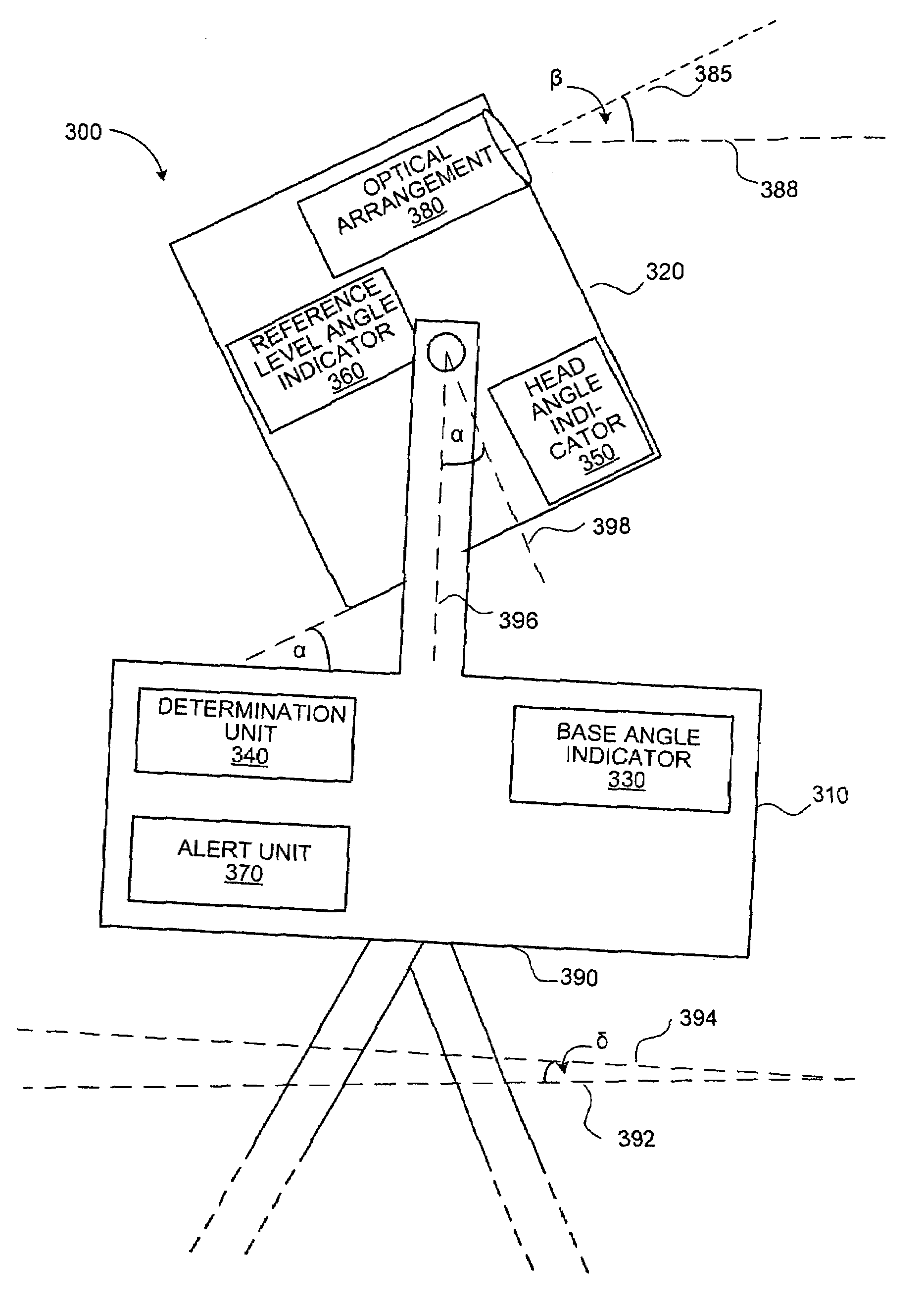
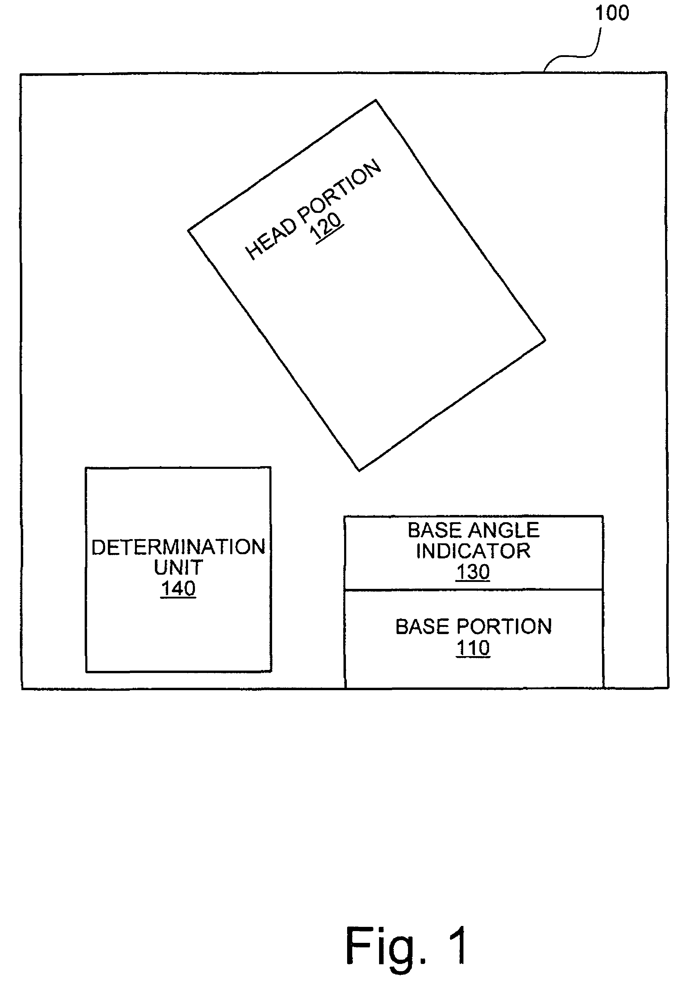
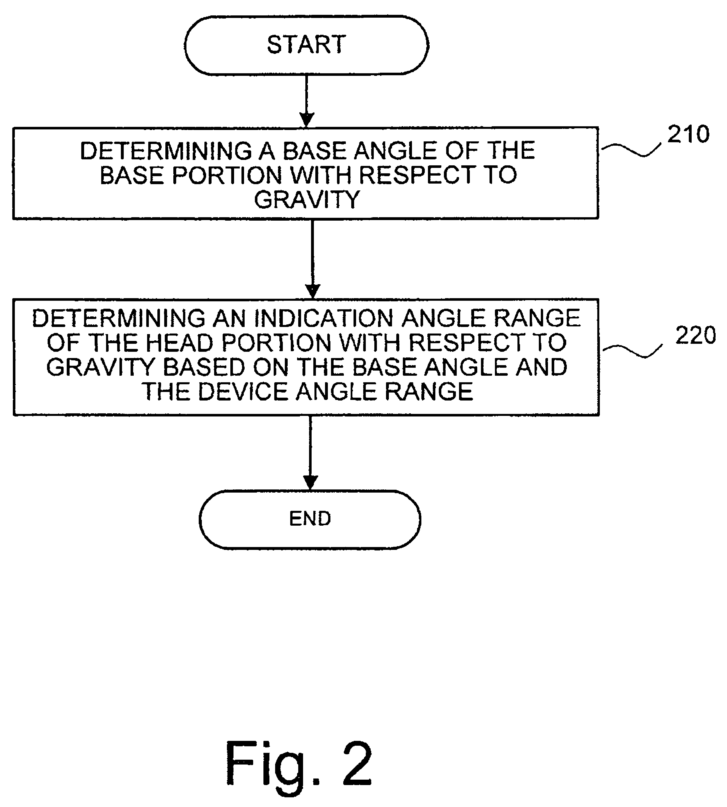
[0030]Embodiments generally relate to an optical instrument having a base portion and a head portion tiltable relative to the base portion and an angle indicator at the base portion so that the leveling state of the optical instrument may be determined or monitored. The leveling state can then be taken into account when measurements with the head portion are performed. For example, in embodiments deviations of a position or orientation of the base portion from a reference position or orientation are determined and taken into account when determining an available angle range of the head portion when in operation under this condition with respect to the reference position or orientation.

[0031]More precisely, in these embodiments, on the basis of a known device angle range of the instrument, i.e....


PUM


Abstract

The present invention relates to an optical instrument with an angle indicator and a method for operating the same enabling simple monitoring of instrument inclination and operation in a large angle range. The optical instrument comprises a base portion, a head portion tiltable relative to the base portion within a device angle range, a base angle indicator attached to the base portion for determining a base angle of the base portion and a determination unit for determining an indication angle range of the head portion based on the base angle and the device angle range.

Description

FIELD OF THE INVENTION[0001]The present invention relates to an optical instrument with an angle indicator and a method for operating the same, and in particular to an optical instrument having a head portion and a base portion with an angle indicator attached thereto.BACKGROUND[0002]Various kinds of optical instruments are commonly employed in various surveying and construction applications and are used for measuring distances and / or angles of objects or for indicating a direction or plane by a laser. Generally an optical instrument is first set up in an absolutely level position in an initial leveling procedure. After the instrument is in the level position, the actual surveying or indicating procedure can start, including calculating any angles of an emitted laser beam of the optical instrument under the condition that the instrument is in the level position.[0003]For example, in construction applications, a laser beam emitted by the instrument can be used as an elevational refer...

Claims


Application Information

Patent Timeline
Patent Type & Authority Patents(United States)
IPC IPC(8): G01C1/00
CPCG01B21/22G01C9/06G01C15/008
Inventor SCHUMACHER, LARS
Owner SPECTRA PRECISION (USA) LLC
Why Eureka
Try Eureka