Inlet bleed heat and power augmentation for a gas turbine engine

a gas turbine engine and heat augmentation technology, applied in the field of gas turbine engines, can solve the problems of higher emissions

Active Publication Date: 2010-11-30
ANSALDO ENERGIA SWITZERLAND AG
View PDF24 Cites 89 Cited by
  • Summary
  • Abstract
  • Description
  • Claims
  • Application Information

AI Technical Summary

Benefits of technology

[0013]In another embodiment, a bi-directional flowing nozzle for passing steam to the compressor discharge plenum or drawing air from the compressor discharge plenum is disclosed. The nozzle comprises an end cap positioned proximate an end of a feed tube. A plurality of holes are arranged about the end cap, with the holes having a rounded edge on one side of the end cap and a sharp edge on the other. The sharp-edge hole opening is located on the side of steam flow from the feed tube and the rounded-edge hole opening is located on the side of air flow from the compressor discharge plenum. The different edge configurations allow for the proper amount of fluid, either air or steam, to flow through the holes and the nozzle.

Problems solved by technology

As such, typically the combustion process is different at lower settings (not optimal) and as a result, emissions are higher.

Method used


Image

  • Inlet bleed heat and power augmentation for a gas turbine engine
  • Inlet bleed heat and power augmentation for a gas turbine engine
  • Inlet bleed heat and power augmentation for a gas turbine engine

Examples


Embodiment Construction

[0025]The subject matter of the present invention is described with specificity herein to meet statutory requirements. However, the description itself is not intended to limit the scope of this patent. Rather, the inventors have contemplated that the claimed subject matter might also be embodied in other ways, to include different steps or combinations of steps similar to the ones described in this document, in conjunction with other present or future technologies. Moreover, although the terms “step” and / or “block” may be used herein to connote different elements of methods employed, the terms should not be interpreted as implying any particular order among or between various steps herein disclosed unless and except when the order of individual steps is explicitly described.

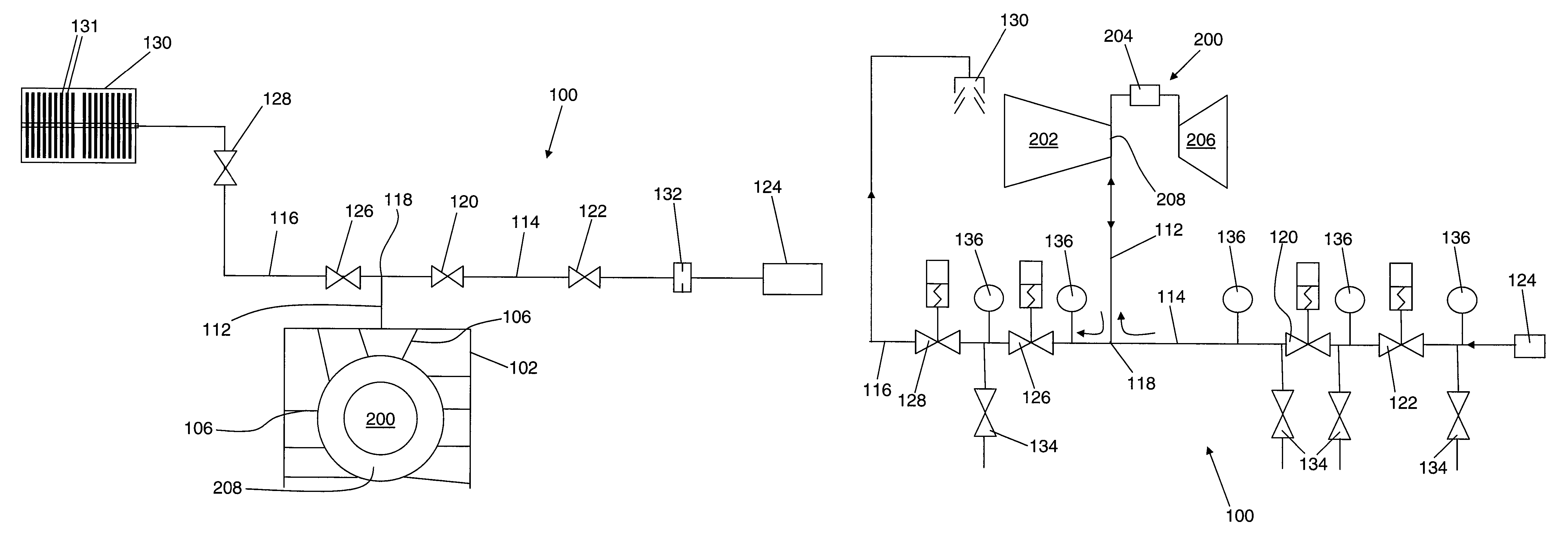
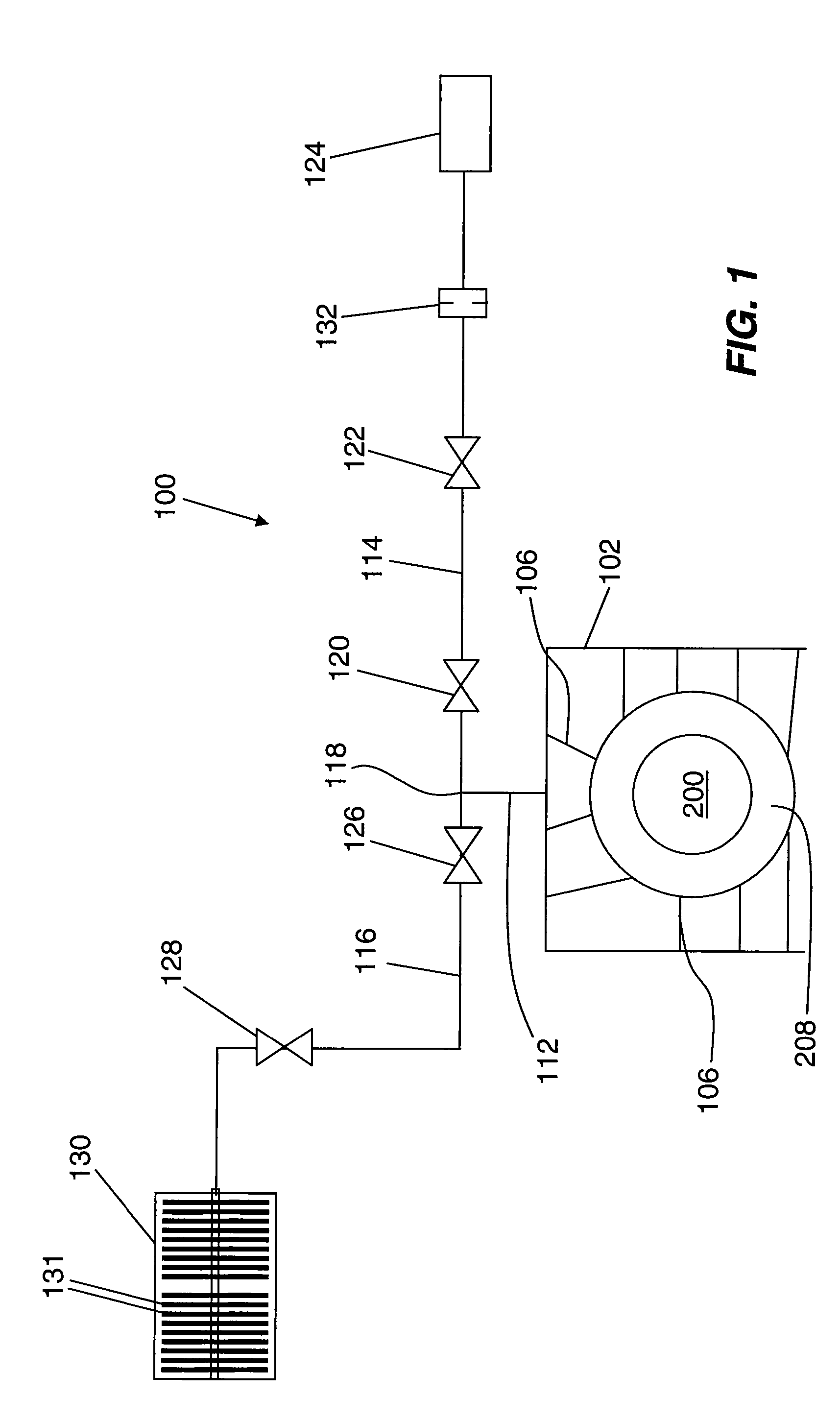
[0026]Referring now to FIG. 1, the present invention provides an embodiment of an inlet bleed heat and steam injection system 100 comprising a manifold 102 extending about at least a portion of a gas turbine engi...


PUM


Abstract

An inlet bleed heat and power augmentation system utilizing a bi-directional and common piping arrangement is disclosed. The piping arrangement includes a plurality of feed tubes arranged to communicate either steam to a compressor discharge plenum or compressed air from the compressor discharge plenum. Various embodiments of the invention are discussed including operation methods.

Description

CROSS-REFERENCE TO RELATED APPLICATIONS[0001]Not Applicable.STATEMENT REGARDING FEDERALLY SPONSORED RESEARCH OR DEVELOPMENT[0002]Not Applicable.TECHNICAL FIELD[0003]The present invention relates to gas turbine engines. More particularly, embodiments of the present invention relate to apparatus and method for increasing engine operational range and improving emissions of a gas turbine engine while simplifying the associated hardware.BACKGROUND OF THE INVENTION[0004]Gas turbine engines operate to produce mechanical work or thrust. Land-based gas turbine engines typically have a generator coupled thereto for the purposes to generating electricity. These generators apply a load to the engine. Land-based gas turbine engines have different modes of operation depending on the load applied to the engine. From an emissions and fuel consumption standpoint, land-based gas turbines are designed to operate most efficiently at a full power condition, also known as baseload, as that operating poin...

Claims


Application Information

Patent Timeline
Patent Type & Authority Patents(United States)
IPC IPC(8): F02C6/04
CPCF02C3/30F02C7/04F02C7/143
Inventor SO, PETERSEWELL, JESSEADAMS, DONALD
Owner ANSALDO ENERGIA SWITZERLAND AG
Why Eureka
Try Eureka