Bandless hearing protector and method

a hearing protector and band-based technology, applied in the field of band-based hearing protectors and methods, can solve the problems of traumatic hearing impairment and even hearing loss, impairments that do not respond to hearing aids or surgery, uncomfortable and difficult to insert correctly, etc., to achieve the effect of attenuating the sound in the human ear

Inactive Publication Date: 2010-11-30
KIMBERLY-CLARK WORLDWIDE INC
View PDF69 Cites 74 Cited by
  • Summary
  • Abstract
  • Description
  • Claims
  • Application Information

AI Technical Summary

Benefits of technology

[0007]In one aspect of the present invention, there is a hearing protection device for the passive attenuation of sound at a single human ear canal, the device including a replacement assembly with an EAM pad that is integrally connected to a pressure pad, and a support frame. A positioning member assists with disposing the hearing protection device into the ear canal.

Problems solved by technology

High level sound vibrations and perhaps particularly the steady recurring sounds or din in industrial operations are known to cause traumatic hearing impairments and even loss of hearing.
Often these types of impairments do not respond to hearing aids or surgery.
While these types of ear plugs may be useful, they can be uncomfortable and difficult to insert correctly.
Furthermore, handling ear plugs to compress, remove or replace may be unsanitary.
While it is easy and more sanitary to temporarily pull an ear plug away from the ear, the conventional headband may have certain drawbacks and deficiencies.
For some persons, ear bands can cause pressure and are uncomfortable to wear for long periods of time.
The headband can be shaped such that portions of the headband may be close to or touching the wearer's head, and can become irritating and uncomfortable to the wearer.
In addition, there is no mechanism for adjusting the headband to allow for varying head sizes.
Unfortunately, as the distance between the headband end increases, so does the tension in the headband.
Accordingly, wearers with relatively large heads may experience discomfort due to this high tension in the headband.

Method used


Image

  • Bandless hearing protector and method
  • Bandless hearing protector and method
  • Bandless hearing protector and method

Examples


third embodiment

[0077]Reference will now be made in detail to embodiments of the invention, one or more examples of which are illustrated in the drawings. Each example is provided by way of explanation of the invention, and not meant as a limitation of the invention. For example, features illustrated or described as part of one embodiment can be used with another embodiment to yield still a It is intended that the present invention include these and other modifications and variations.

first embodiment

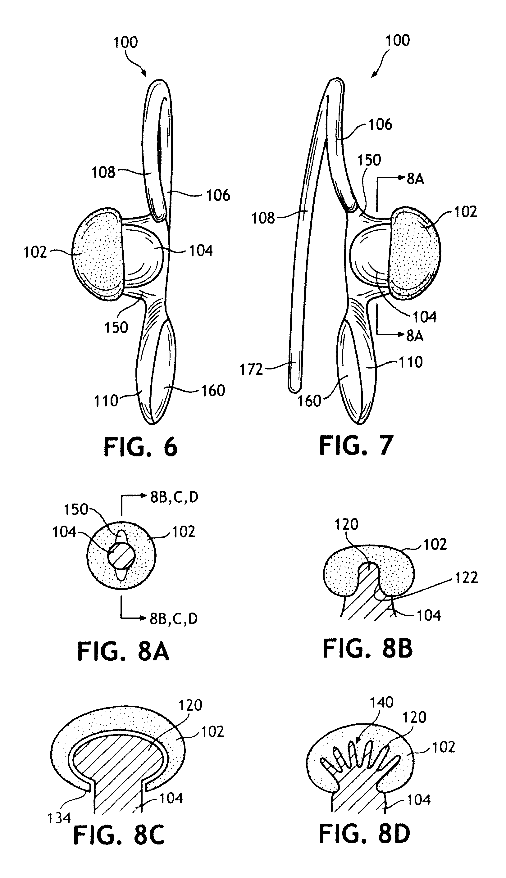
[0078]As shown in FIGS. 6-7, hearing protector 100 desirably has a unitary construction, with the possible exception of the plug 102. The neck 104, shoulder 106, handle 110, and arm 108 may be molded from a plastic material having the following characteristics: flexible enough to move the arm 108 to the backside of pinna 12 as neck 104 is positioned near the ear canal 26; durable enough to be used more than one time; moldable, as by injection molding or the like; and steady-state in that it does not exhibit significant loss of stiffness under a continuous load, allowing neck 104 and plug 102 to maintain an effective force toward the ear canal 26. Desirably, a material such as polyethylene is used. However, it is contemplated that the ear clip portion of hearing protector 100 may be manufactured from nylon, plastics such as polypropylene, polyvinyl chloride, polycarbonate; metals such as titanium, steel, or aluminum composites; or elastomer such as silicon, thermoplastic elastomer (T...

second embodiment

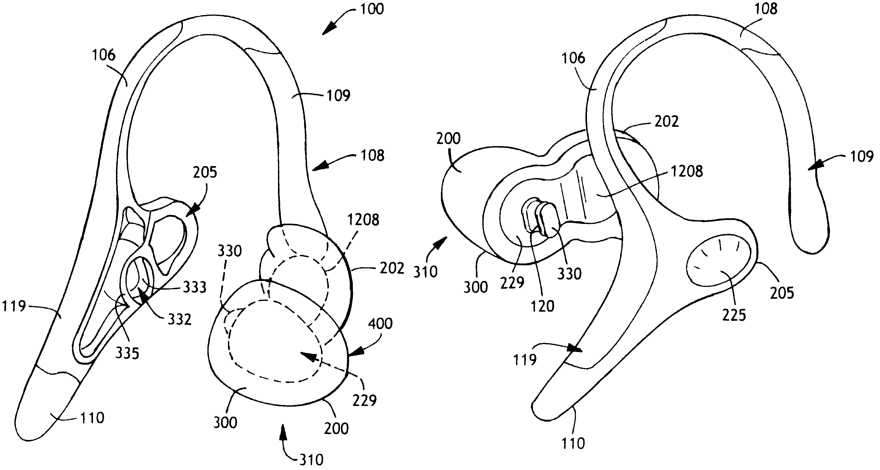
[0146]Referring now to FIGS. 36-39, shown is a hearing protector 100 with replacement assembly 310. The view of FIG. 37 is a cross-sectional view of the replacement assembly 310 taken at the longitudinal axis 302 of the x-y plane. The EAM pad 200 on this particular replacement assembly 310 has a stepped domal shape. The stepped domal shape is similar to the domal shape except that it has an added flange 420 surrounding the edge 311 of the EAM pad 200. This flange 420 may be either more or less prominent in both height 424 and thickness 426. For example, the flange 420 shown in FIG. 40 has both a height 424 and thickness 426 that is greater in dimension than that shown in FIG. 36. The purpose of flange 420 is seal the opening of the ear canal 26 to block sound from entering the ear canal.

[0147]As with the previous embodiment, there exists an obtuse angle 402 between the vertical axis 410 and the exposed surface 408 of the pressure plate 1208 (see FIG. 39). However, it is noted that w...


PUM


Abstract

A hearing protection device and method of use intended for a human ear. A plug member caps or enters ear canal, and may be shaped to conform to the external auditory meatus. The plug member may be part of a replacement assembly. The device is biased at least in part by a pressure pad to provide some force against the plug member. An optional handle may be provided to assist with temporarily pulling the plug member away from the ear canal or providing adjustment. An optional bow member clips about the pinna. The device may be adapted for use as an ear phone.

Description

[0001]This application is a continuation-in-part of application Ser. No. 11 / 799,264 filed Nov. 30, 2007 now U.S. Pat. No. 7,648,005, and application Ser. No. 11 / 821,391 filed on Jun. 22, 2007.BACKGROUND OF THE INVENTION[0002]High level sound vibrations and perhaps particularly the steady recurring sounds or din in industrial operations are known to cause traumatic hearing impairments and even loss of hearing. Often these types of impairments do not respond to hearing aids or surgery. As would be expected, there are numerous types of hearing protectors for noise deadening or noise reduction.[0003]One type of conventional hearing protection device are foam ear plugs that may be compressed and inserted into the ear, and then allowed to expand to fit the ear canal. While these types of ear plugs may be useful, they can be uncomfortable and difficult to insert correctly. Furthermore, handling ear plugs to compress, remove or replace may be unsanitary.[0004]Another type of conventional he...

Claims


Application Information

Patent Timeline
Patent Type & Authority Patents(United States)
IPC IPC(8): H04R25/02A61F11/08H04R25/00A61F11/06
CPCA61F11/08A61F11/12H04R1/1016H04R1/105H04R1/1066
Inventor LEONG, WAIHONGGEHLING, STEVEN CRAIG
Owner KIMBERLY-CLARK WORLDWIDE INC
Why Eureka
Try Eureka