Vehicle body structure having fuel tank and canister

a technology of vehicle body and canister, which is applied in the direction of tank vehicles, transportation and packaging, transportation items, etc., can solve the problems of front cross-member, > interfering with each other, and achieve the effects of improving the perception of the quality of the vehicle interior, reducing the distance to the lower surface of the seatback, and reducing the size of the piping carrier

Inactive Publication Date: 2010-11-30
HONDA MOTOR CO LTD
View PDF9 Cites 17 Cited by
  • Summary
  • Abstract
  • Description
  • Claims
  • Application Information

AI Technical Summary

Benefits of technology

[0006]An object of the present invention is to provide a piping structure for a fuel tank that can greatly increase the capacity of a fuel tank and that can be arranged between canisters without compromising the capacity of the fuel tank.
[0008]Since the underbody is provided with the expanded portion, part of the ceiling plate portion of the fuel tank can be positioned inside the expanded portion, and the capacity of the fuel tank can be increased.
[0010]The expanded portion is preferably provided with a groove-shaped interior console member. Therefore, the perception of quality of the vehicle interior can be improved.
[0012]It is preferred that the rear cross-member be polygonal in cross section normal to the longitudinal direction, and a height of a front wall portion adjacent to the seatback be less than a height of a rear wall portion that faces the front wall portion. Therefore, a sloping upper wall portion that runs from the front wall portion to the rear wall portion is formed; and the distance to the seatback lower surface can be increased and the piping carrier can be made smaller without compromising the strength of the rear cross-member.
[0013]Preferably, the seatback lower surface has a concave portion formed in a shape of a groove so that the expanded portion fits when the seatback has been brought forward and folded. Therefore, the seatback can be brought forward and folded without interfering with the expanded portion. When the seatback is furthermore brought forward and folded, the expanded portion that fits the groove-shaped concave portion acts as a stop and can restrict the distance that the seatback can be folded forward.
[0014]In a preferred form, the fuel tank has an upper portion, while the upper portion of the fuel tank is positioned inside the expanded portion. The fuel tank capacity is increased.

Problems solved by technology

However, there is a problem in that the tube and the front cross-member 204 interfere with each other if an attempt is made to place the tube in a position further above the upper surface 207 of the fuel tank 206.

Method used


Image

  • Vehicle body structure having fuel tank and canister
  • Vehicle body structure having fuel tank and canister
  • Vehicle body structure having fuel tank and canister

Examples


Embodiment Construction

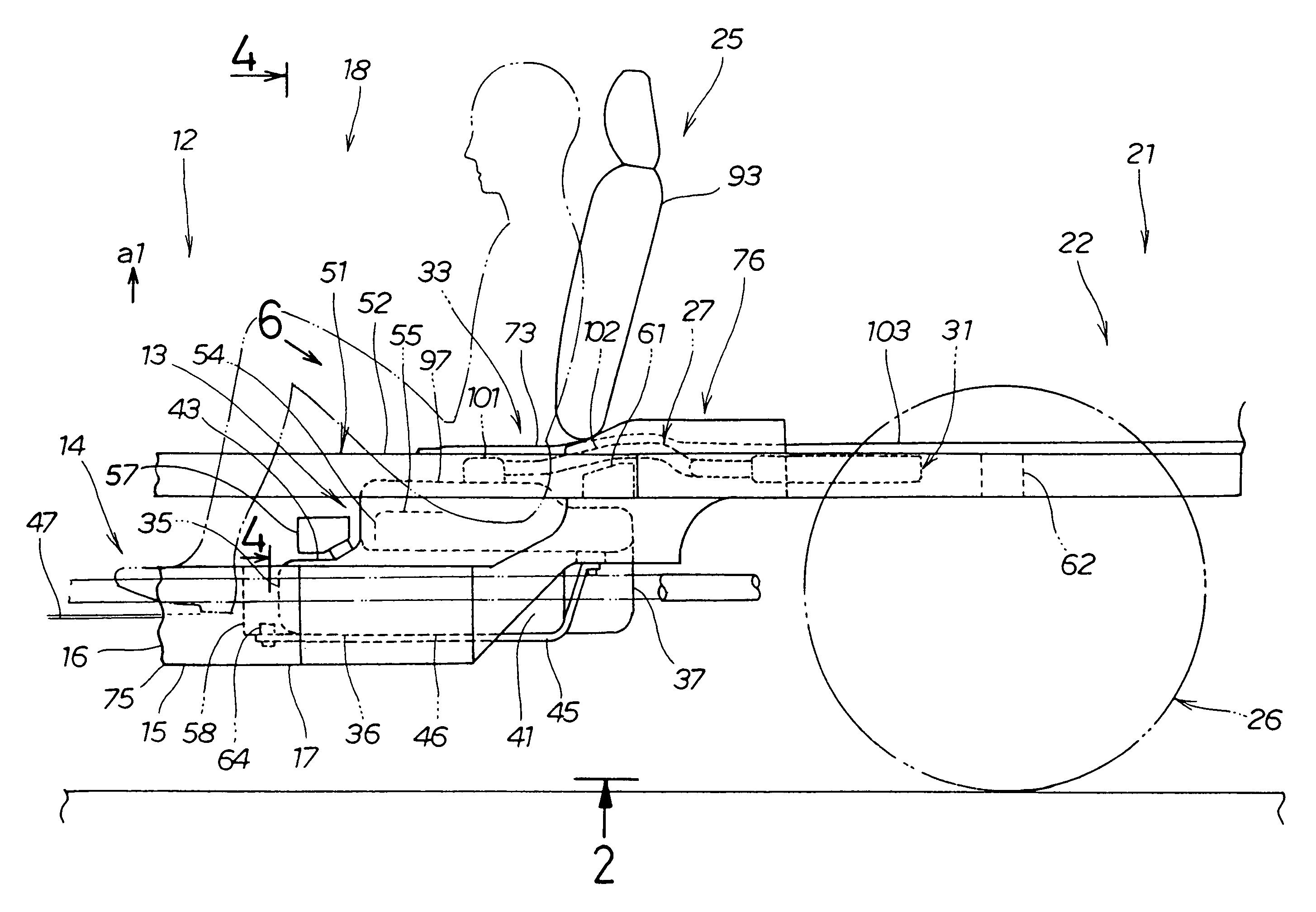
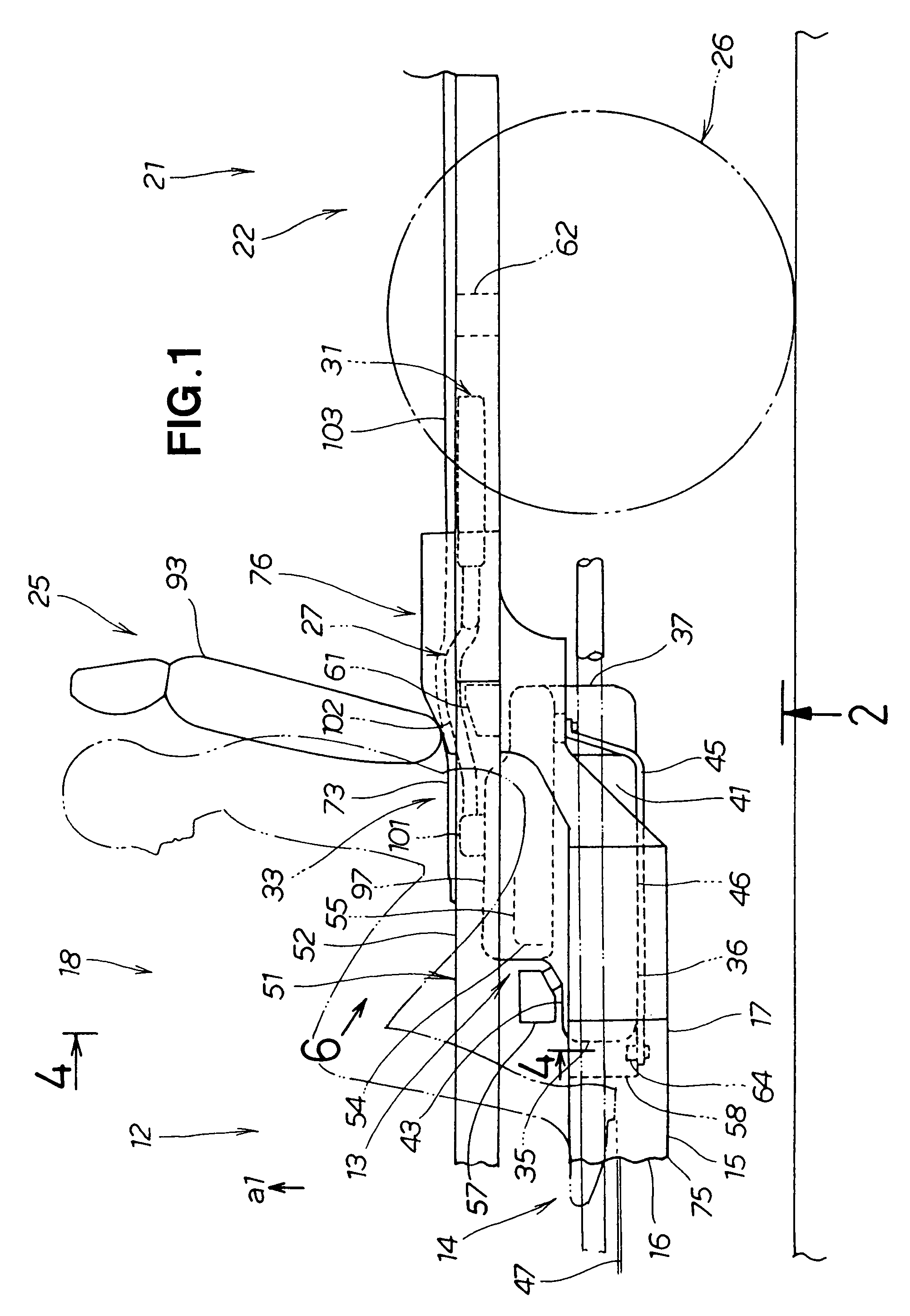
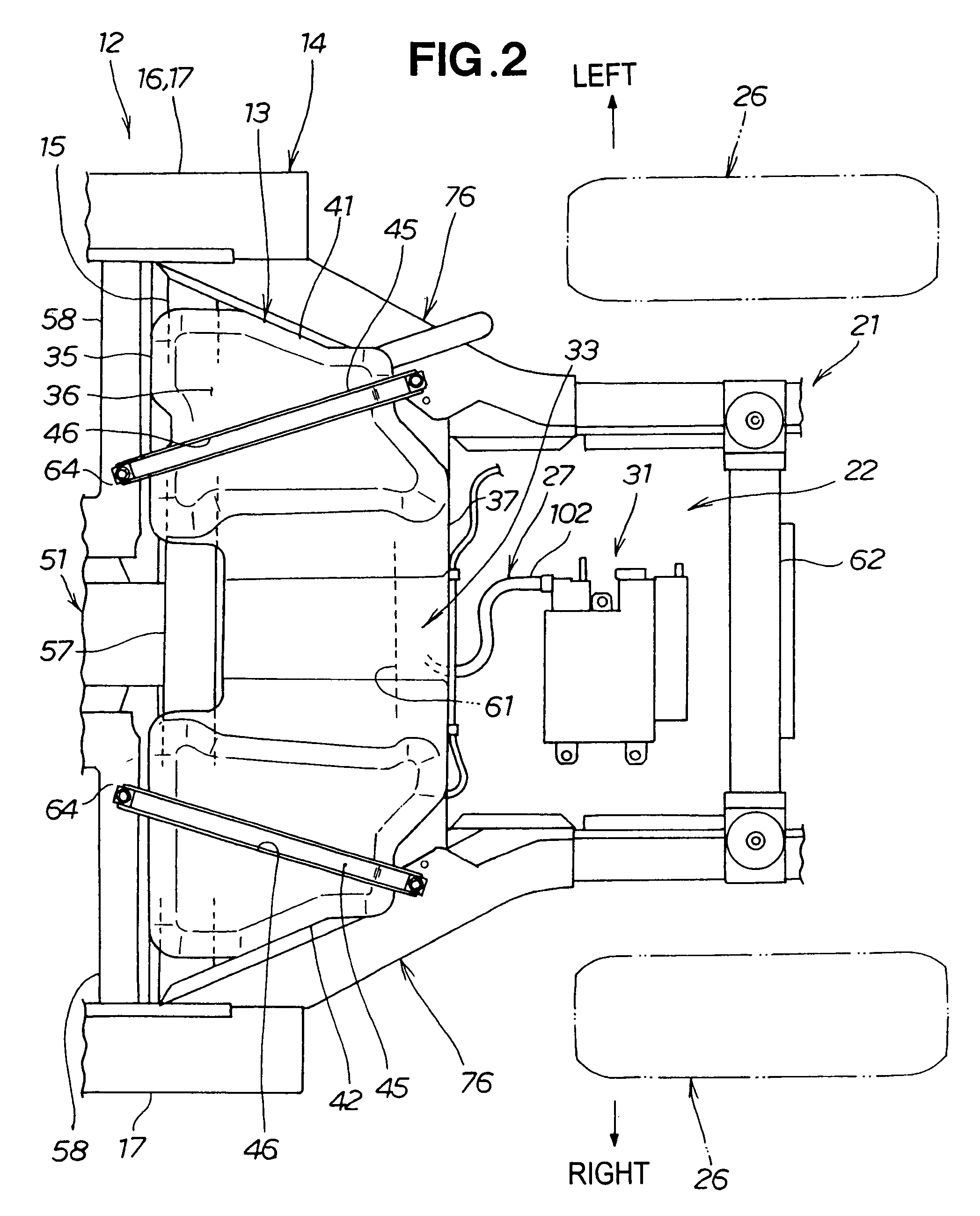
[0026]Referring to FIGS. 1 and 2, a vehicle body structure 33 having a fuel tank 13 and a canister 31 is formed on an underbody 15 that constitutes the floor of a vehicle body 14.

[0027]A vehicle 12 is provided with the underbody 15; a side sill 17, which is connected to the underbody 15 and is the lower portion of a side body 16; a vehicle interior 18; a rear body 21 and a luggage compartment 22 disposed behind the vehicle interior 18; a seat (rear seat) 25 disposed to the rear inside the vehicle interior 18; a rear wheel 26 supported by the underbody 15 via a suspension device (not shown); the canister 31 connected to the fuel tank 13 via a communication path 27; and the communication path 27.

[0028]The fuel tank 13 has a front plate portion 35, a bottom plate portion 36, a rear plate portion 37, a left-side first lateral plate portion 41, a right-side second lateral plate portion 42, and a ceiling plate portion 43.

[0029]A groove-shaped banding groove portion 46 on which a band memb...


PUM


Abstract

A vehicle body structure with a fuel tank and canister is disclosed. A communication path connecting a fuel tank with a canister is provided to pass between a rear cross-member and an expanded portion of an underbody.

Description

FIELD OF THE INVENTION[0001]The present invention relates to a vehicle body structure in which a communication path is formed for accommodating a pipe that provides communication between a fuel tank and a canister for recovering fuel gas vapors from the fuel tank.BACKGROUND OF THE INVENTION[0002]Vehicles generally have a fuel tank and a canister disposed below an underbody that constitutes the floor of the vehicle body, and the fuel tank and canister are connected by a pipe through which fuel gas passes.[0003]The canister is disposed in the vicinity of the fuel tank, e.g., between two cross-members that are positioned behind the fuel tank, in order to recover evaporated gas inside the fuel tank, and is thereby protected from rear collision. A mounting structure of a canister is known in, e.g., Japanese Patent Application Laid-Open Publication No. 2004-143966 (JP 2004-143966A). FIG. 10 hereof shows the mounting structure of the canister disclosed in JP 2004-143966A. The mounting stru...

Claims


Application Information

Patent Timeline
Patent Type & Authority Patents(United States)
IPC IPC(8): B60P3/22
CPCB60K15/03504B60K15/063B60K2015/03557
Inventor KOBAYASHI, KAZUHIROMUROTA, MASASHIOHISHI, TAKESHI
Owner HONDA MOTOR CO LTD
Why Eureka
Try Eureka