Method and system for determining objects poses from range images

a range image and object technology, applied in the field of computer vision, can solve the problems of lack of robustness to illumination variation, appearance change, and most methods need manual initialization, and achieve the effect of reducing the error function

a range image and object technology, applied in the field of computer vision, can solve the problems of lack of robustness to illumination variation, appearance change, and most methods need manual initialization, and achieve the effect of reducing the error function

US7844105B2Inactive Publication Date: 2010-11-30MITSUBISHI ELECTRIC RES LAB INC

Image

  • Method and system for determining objects poses from range images
  • Method and system for determining objects poses from range images
  • Method and system for determining objects poses from range images

Examples


Embodiment Construction

[0024]Method and System Overview

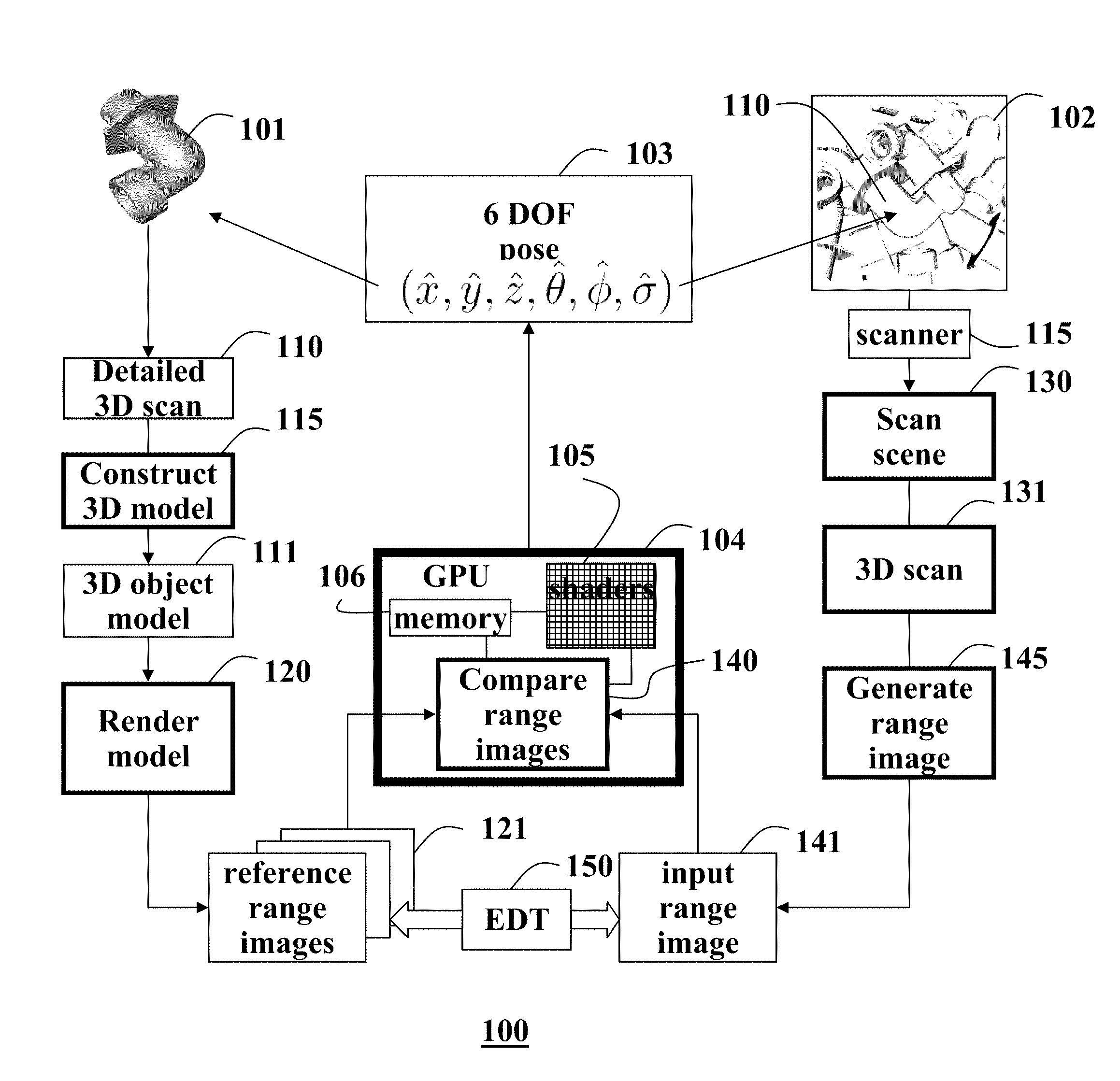
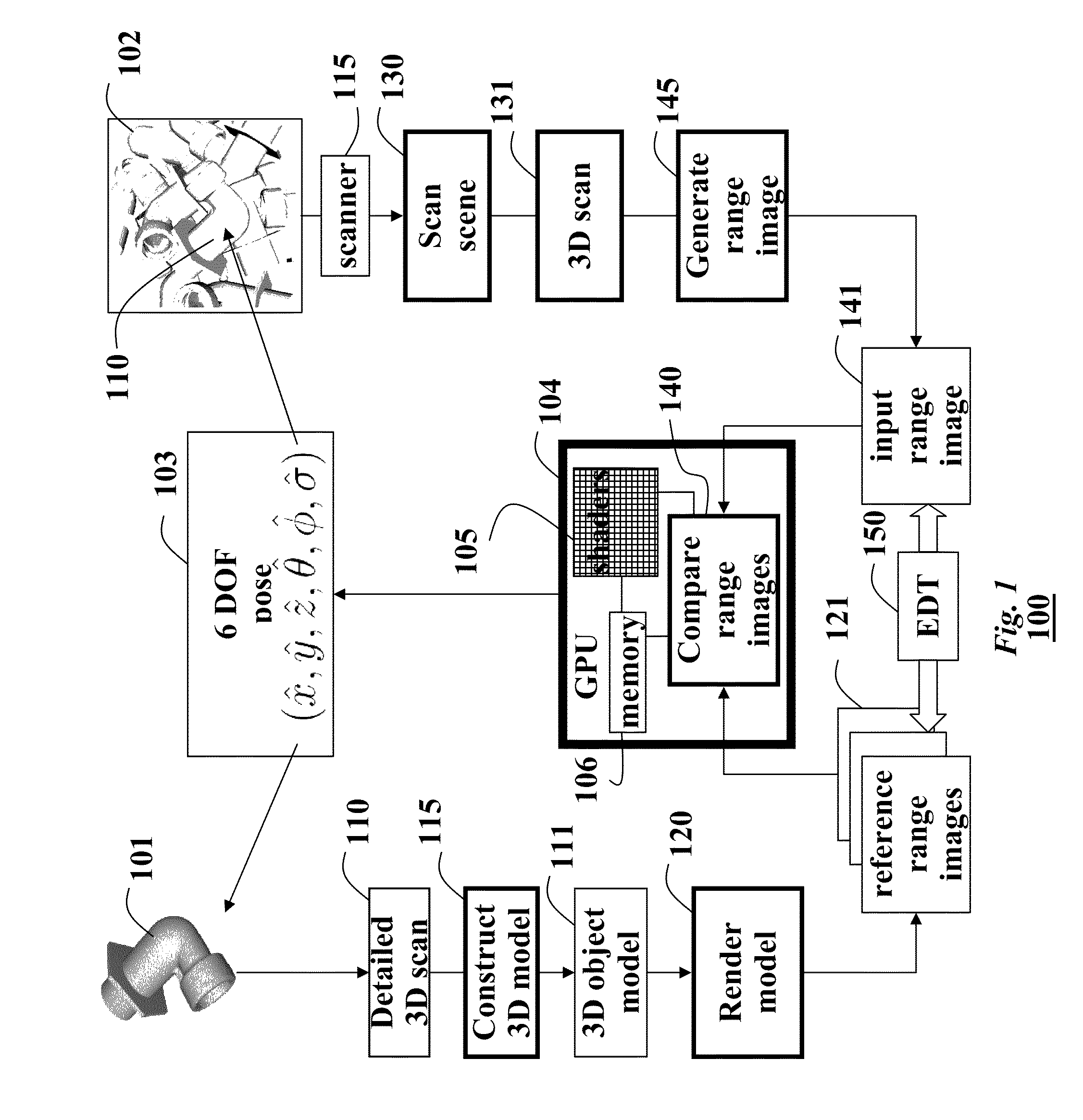
[0025]FIG. 1 shows a method and system 100 for determining a pose of an input object 110 of interest from range images 141 according to an embodiment of our invention. The method runs entirely on a graphics processing unit (GPU) 104. The massive data-parallel processing on the GPU makes our method much simpler and more efficient than, more complex CPU-based methods. The method is fully automatic and does not require any initial pose guesses. Even though we compare several thousand reference images, the pose determination takes about one second. Therefore, the method is suitable for real-time applications.

[0026]The pose can be used by other applications, for example, a robotic application that mechanically manipulates the object.

[0027]Preprocessing

[0028]During pre-processing, a reference object of interest 101 is scanned 110 to construct 115 detailed 3D model 111 of the reference object. The reference object 101 is similar to the input object 110. The ...


PUM


Abstract

A method and system determines a pose of an object by comparing an input range image acquired of a scene including the input object to each of a set of reference range image of a reference object, such that each reference range images has an associated different pose, and the reference object is similar to the input object. Then, the pose associated with the reference range image which best matches the input range image is selected as the pose of the input object.

Description

FIELD OF THE INVENTION[0001]This invention relates generally to computer vision and more particularly to determining poses of objects front images acquired of the objects.BACKGROUND OF THE INVENTION[0002]A common task in computer vision applications is to estimate a pose of objects from images acquired of a scene. Herein, pose is defined as the 6-DOF location and orientation of an object. Pose estimation in scenes with clutter, e.g., unwanted objects and noise, and occlusions, e.g., due to multiple overlapping objects, can be quite challenging. Furthermore, pose estimation in 2D images and videos is sensitive to illumination, shadows, and lack of features, e.g., objects without texture.[0003]Pose estimation from range images, in which each pixel includes an estimate of a distance to the objects, does not suffer from these limitations. Range images can be acquired with active light systems, such as laser range scanners, or active light stereo methods. Range images are often called ra...

Claims


Application Information

Patent Timeline
30 Nov 2010
Publication
US7844105B2
IPC
G06K9/00; G01B11/00; G01B11/26; G06T1/00; G06T15/00
CPC
G06K9/00208; G06T7/0044; G06T2207/10028; G06T7/74; G06V20/647
Inventors
PFISTER, HANSPETER; GERMANN, MARCEL