
Method and system for determining poses of objects from range images using adaptive sampling of pose spaces

a range image and adaptive sampling technology, applied in the field of computer vision, can solve the problem that most methods need manual initialization, and achieve the effect of reducing the error function

Inactive Publication Date: 2010-11-30
MITSUBISHI ELECTRIC RES LAB INC
View PDF5 Cites 10 Cited by
  • Summary
  • Abstract
  • Description
  • Claims
  • Application Information

AI Technical Summary

Benefits of technology

Enables accurate and efficient pose estimation in complex scenes without initial pose estimates, overcoming sensitivity to illumination and occlusions, and achieving real-time processing by leveraging GPU parallelism and adaptive sampling.

Problems solved by technology

Although many methods are known for pose estimation, most methods need manual initialization and are sensitive to illumination variation, appearance change, and partial occlusions.

Method used


Image

  • Method and system for determining poses of objects from range images using adaptive sampling of pose spaces
  • Method and system for determining poses of objects from range images using adaptive sampling of pose spaces
  • Method and system for determining poses of objects from range images using adaptive sampling of pose spaces

Examples


Embodiment Construction

Method and System Overview

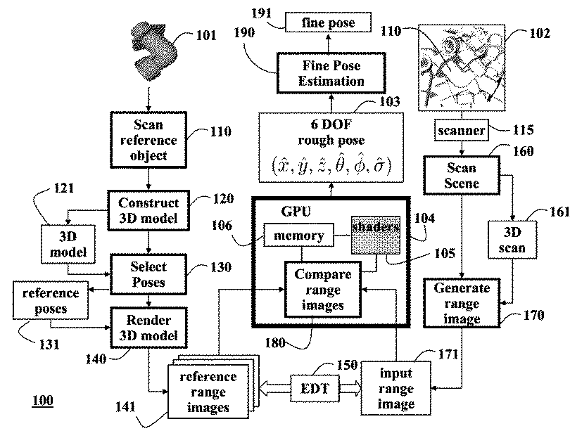
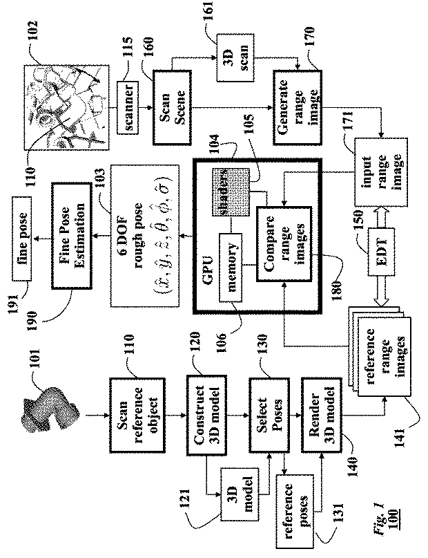
[0050]FIG. 1 shows a method and system 100 for determining a pose of an object 110 according to embodiments of our invention. The method uses range images 171, reference images 141, and a 3D model 121 of the object.

[0051]The method is performed, in part, on a graphics processing unit (GPU) 104. The massive data-parallel processing on the GPU makes our method much simpler and more efficient than more complex general purpose computer based methods. Our method is fully automatic and does not require an initial estimate of the pose. Even though we compare several thousand reference images, the pose determination can be performed in real-time.

[0052]The pose can be used by other applications, for example, a robotic application that mechanically manipulates the object.

[0053]Preprocessing

[0054]During pre-processing, a reference object 101 is scanned 110 in detail to construct 120 a 3D model 121 of the reference object. The reference object 101 is identical to the i...


PUM


Abstract

A method for determining a pose of an object from a range image is presented. A distribution of poses for an object is determined from a model of the object. A set of reference poses is selected according to the distribution, such that more reference poses are selected for more probable poses than less probable poses. A reference image for each reference pose is generated, and the reference pose used to generate the reference image that best matches a range image including the object is assigned as the pose of the object.

Description

RELATED APPLICATION[0001]This application is a Continuation in Part of U.S. patent application Ser. No. 11 / 738,642, “Method and System for Determining Objects Poses from Range Images” filed by Pfister et al. on Apr. 23, 2007, and incorporated by reference.FIELD OF THE INVENTION[0002]This invention relates generally to computer vision and more particularly to determining poses of objects from images acquired of the objects using adaptive sampling of the pose spaces of the objects.BACKGROUND OF THE INVENTION[0003]A common task in computer vision applications is to estimate a pose of objects from images acquired of a scene. Herein, the pose is defined as the 6-DOF location and orientation of an object. Pose estimation in scenes with clutter, e.g., other objects, noise, and occlusions, e.g., due to multiple overlapping objects, can be quite challenging. Furthermore, pose estimation in 2D images and videos is sensitive to illumination variation, shadows, and lack of features, e.g., shiny...

Claims


Application Information

Patent Timeline
Patent Type & Authority Patents(United States)
IPC IPC(8): G06K9/00
CPCG06T7/0046G06T7/0048G06T2200/28G06T2207/10028G06T2207/30164G06T7/75G06T7/77G06T2207/20104
Inventor PFISTER, HANSPETERPARK, IN KYUGERMAN, MARCELBREITENSTEIN, MICHAEL D.
Owner MITSUBISHI ELECTRIC RES LAB INC
Learn More