Vehicular wiper frame

a wiper frame and wiper technology, applied in the field of wiper frames, can solve the problems of unchangeable wiper arms, premature wear of blade areas, and uneven distribution along the length of blades, so as to improve the wiping effectiveness and firm contact of the blades, prevent judder and streaking, and improve the effect of wiping effectiveness

Inactive Publication Date: 2010-12-07
PARK LTD
View PDF4 Cites 15 Cited by
  • Summary
  • Abstract
  • Description
  • Claims
  • Application Information

AI Technical Summary

Benefits of technology

[0023]Another object of the present invention is to provide a wiper frame and a rubber blade that can maintain a predetermined lean of the entire wiper to prevent judder and streaking and maintain reliable contact with a windshield.
[0024]A further object of the present invention is to provide a wiper frame and a rubber blade that maintain an even load distribution across the rubber blade on a windshield surface to increase wiping effectiveness and firm contact of the blade on the windshield, while preventing noise induced by judder and lift while the vehicle is in motion.

Problems solved by technology

In the structure of this type of wiper, because the load on the blade is applied at certain points on the blade, it is unevenly distributed along the length of the blade.
This unevenness causes premature wear of blade areas that are more compressed, while less compressed areas are prone to streak or overshoot the windshield glass underneath.
The problem with the foresaid wiper is that the aggregate tension of the two tension springs 18 and 18a and the rubber cover 21 necessitate the wiper arm maintaining an increased load on the wiper for the wiper to be operationally effective, unduly stressing the mechanism.
Also, this type of wiper is not interchangeable with existing wiper arms on vehicles that have a tension present for the previously mentioned multi-point-type wiper blade.
Furthermore, because the wiper requires the rubber spoiler-cum-cover to complete the formation thereof, the latter item cannot be omitted.
Therefore a separately formed spoiler is required, complicating the overall structure, and creating the possibility of vibration or judder caused by the spoiler and wind noise when pressed against a windshield.
However, although the rubber blade is structurally prevented from lifting without a separately installed spoiler, the blade is not disposed vertically on the glass, so that its clearing capability diminishes.
That is, when the wiper operates and moves across the surface of the glass about the pivoting pressure center of the motor, the blade does not continuously contact the surface of the windshield at a perpendicular angle, thus failing to impart adequate contact between the blade and the windshield.
That is, the angle of the pressing force imparted on the rubber blade by the wiper arm cannot maintain a vertical disposition with respect to the surface of the glass, so that the wiper's contact, wiping ability, secure disposition, etc. are insufficiently maintained.

Method used


Image

  • Vehicular wiper frame
  • Vehicular wiper frame
  • Vehicular wiper frame

Examples


first embodiment

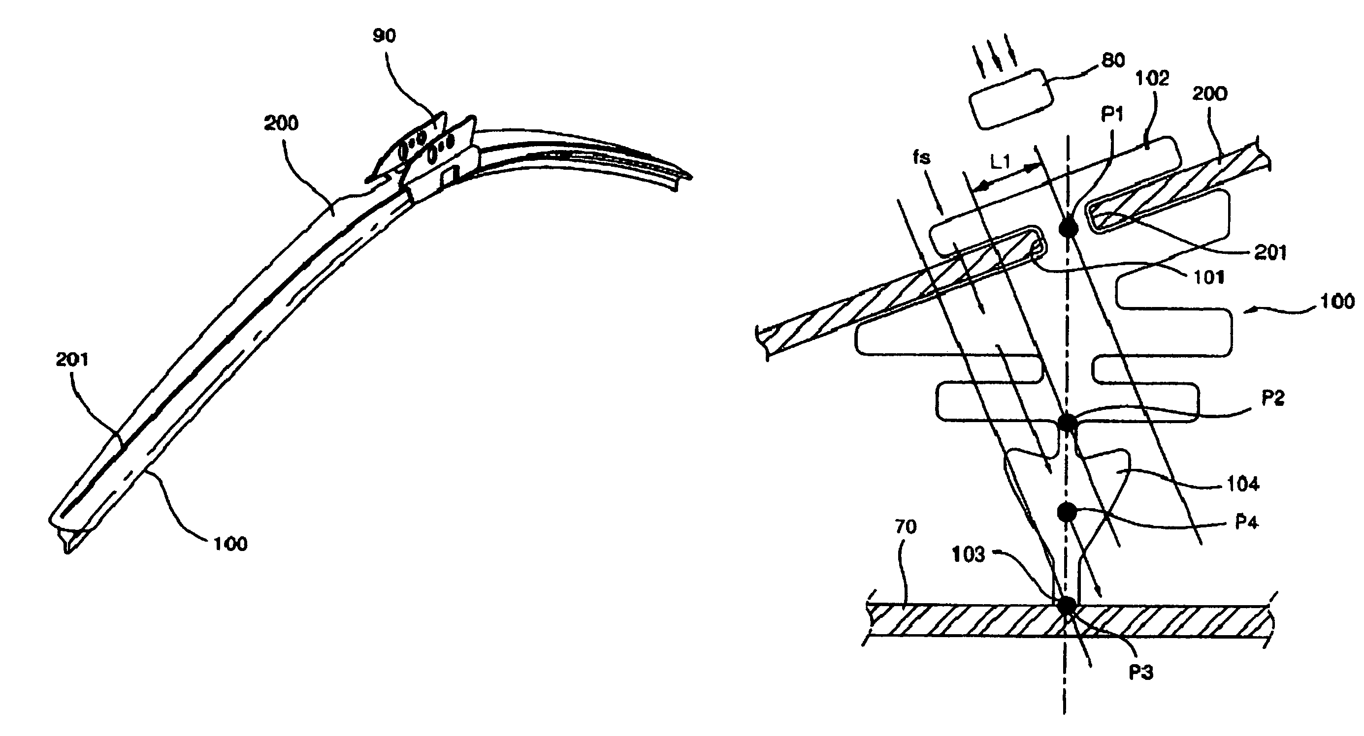
[0065]Referring to FIGS. 9 through 12, a rubber blade 100 installed to a frame 200 according to the present invention has a mounting portion 102 at its top that is disposed at a predetermined angle and installed to the frame 200. The bottom portion of the rubber blade 100 has a wiping portion 104 that extends from the mounting portion 102 and has a contact surface 103 that contacts the windshield surface 70.

[0066]Here, the centers of the mounting portion 102 and wiping portion 104 are offset by a distance L1 from each other, due to the position of the slot 201 of the frame 200. When the pressing force (fs) or (fs1-fs2) is applied by the wiper arm 80, it passes through the center P4 of the wiping portion 104. Thus, the slant of the slot 201 of the frame 200 and its shape take into consideration and are formed at the point of applied pressure of the wiper arm.

[0067]According to the shape and position of the slot 201 of the frame 200, an offset is formed between the mounting portion 10...

second embodiment

[0072]Referring to FIGS. 13 through 15, the upper portion of the rubber blade 100 has the mounting portion 102 that is disposed and installed at a predetermined angle with respect to the frame 200a, and the lower end of the rubber blade 100 includes a wiping portion 104 extending from the mounting portion 102 and having a contact surface 103 that contacts the windshield surface 70.

[0073]The mounting portion 102 and the wiping portion 104 are formed such that their respective centers are offset by a predetermined distance L1. When a pressing force (fs) is applied by the wiper arm 80, it passes through the center point P4 of the wiping portion 104. Accordingly, the angle and shape of the rubber blade is formed to be at the center of pressure applied by the wiper arm.

[0074]The offset distance L1 between the mounting portion 102 and wiping portion 104 of the rubber blade 100 is set as the distance between the center point P1 of the mounting portion 102 and the center point P2 of the wip...


PUM


Abstract

A vehicular wiper frame and a rubber blade that mounts to the frame are provided. The frame allows the rubber blade to exert vertical pressure against a windshield for a secure contact between the two surfaces. The frame includes a slot in which a mounting portion of the rubber blade is mounted, creates a predetermined offset between the centers of the mounting portion and a wiping portion of the rubber blade therebelow, and is formed in a position so that the pressure of the wiper arm can fall at the center of the wiping portion. The mounting portion is slanted and installed at a predetermined angle to the frame, and the wiping portion extends from the mounting portion and includes a contact surface contacting the windshield surface. The pressing force of the wiper arm 80 passes through the central point of the wiping portion.

Description

BACKGROUND OF THE INVENTION[0001]1. Field of the Invention[0002]The present invention relates to a vehicular wiper frame and a rubber blade mounted thereon, and more particularly, to a frame that can allow a rubber blade lying against a vehicular windshield to exert vertical pressure against the windshield. By maintaining the pressure against the windshield in a substantially vertical direction, the moment of a force generated between the wiping surface of the rubber blade and the surface of the windshield is minimized and a secure contact between the two surfaces is maintained.[0003]2. Description of the Related Art[0004]An automotive wiper is operated by a wiper motor through a mechanical linkage that moves the wiper arm back and forth in a predetermined arc. Disposed on the end of the wiper arm is a detachably mounted wiper frame to which a wiper blade made of rubber is attached.[0005]Conventional wipers attached to wiper arms include a skeletal frame and a blade portion mounted ...

Claims


Application Information

Patent Timeline
Patent Type & Authority Patents(United States)
IPC IPC(8): B60S1/38
CPCB60S1/38B60S1/3808B60S1/3879B60S1/381B60S2001/382
Inventor PARK, SE-HEON
Owner PARK LTD
Why Eureka
Try Eureka