
Die cushion controller

a controller and cushion technology, applied in the direction of electric programme control, instrumentation, shape safety devices, etc., can solve the problems of inconvenient control and inherent limitations of this approach, and achieve the effect of improving the follow-up performan

Inactive Publication Date: 2010-12-07
FANUC LTD
View PDF16 Cites 11 Cited by
  • Summary
  • Abstract
  • Description
  • Claims
  • Application Information

AI Technical Summary

Benefits of technology

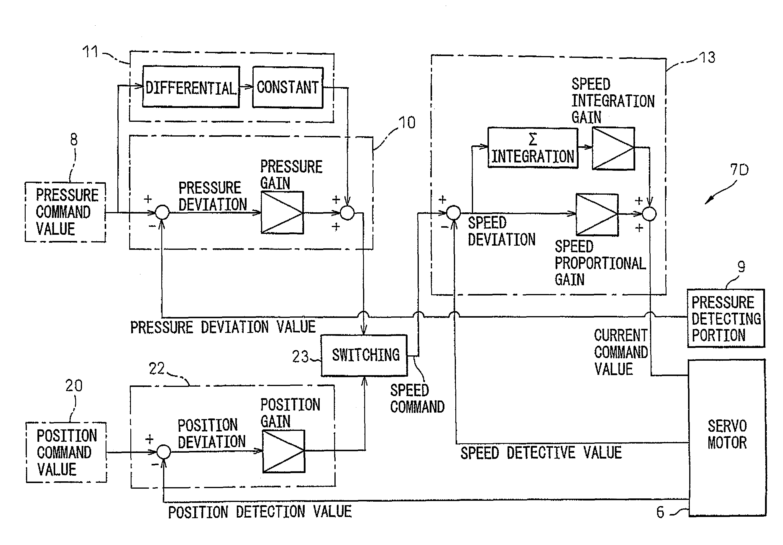
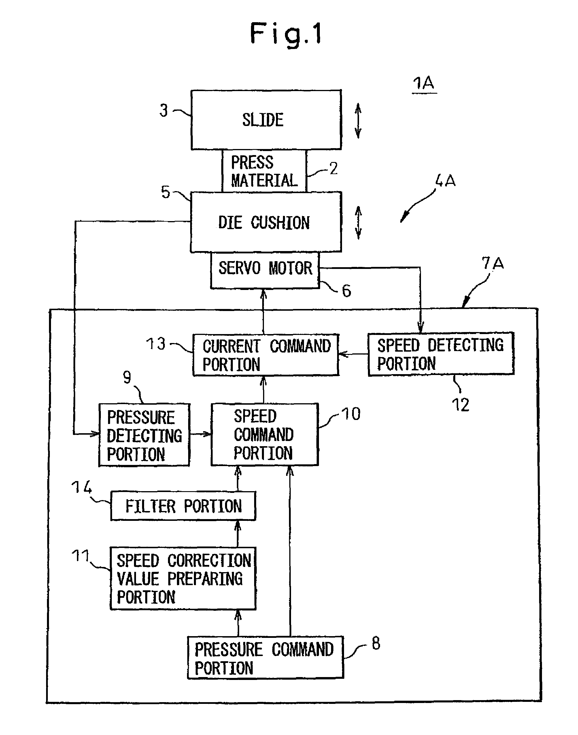
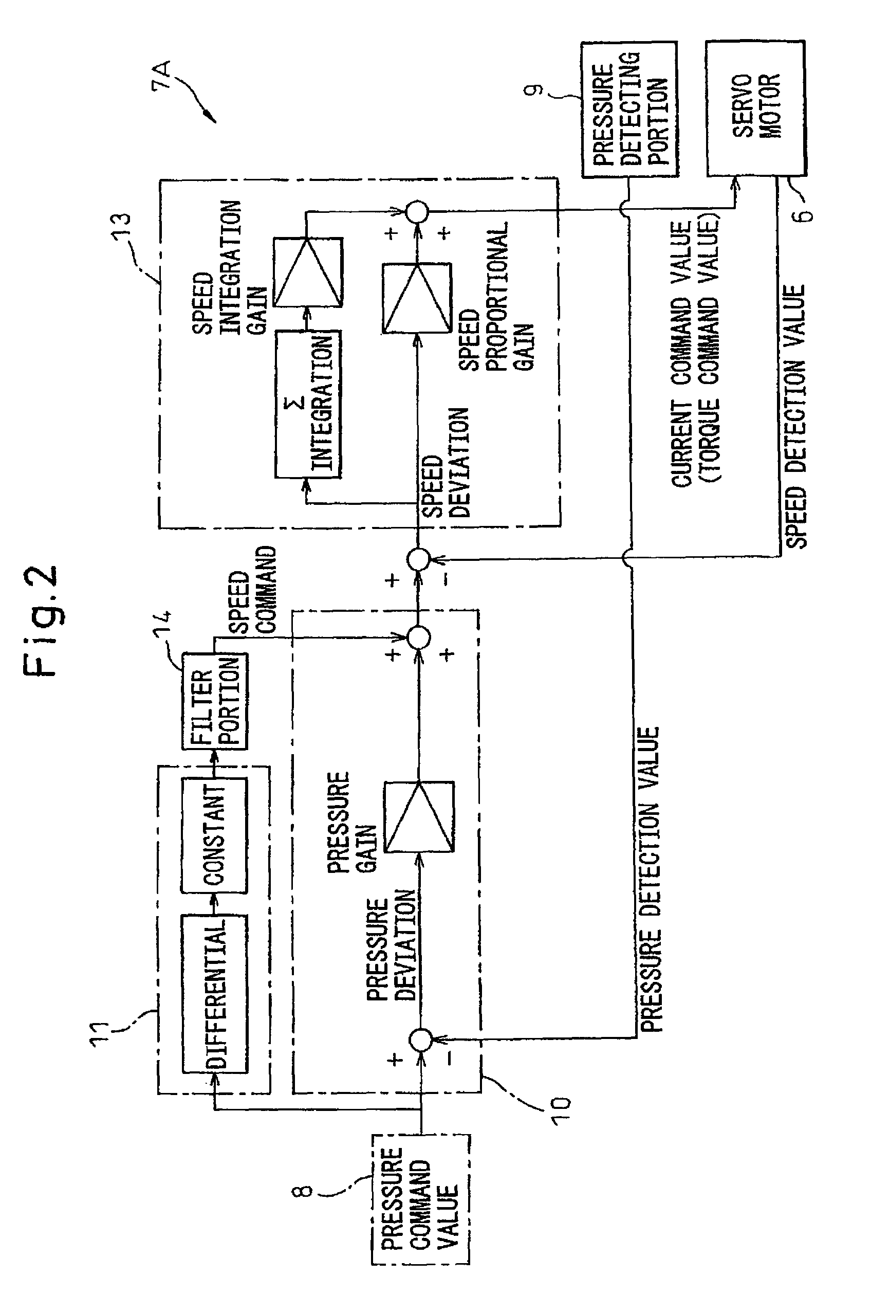
The present invention provides a die cushion controller for driving a die cushion disposed in opposition to a slide of a press machine by controlling a servo motor. The controller includes a pressure command portion, a pressure detecting portion, a speed correction value preparing portion, and a current correction value preparing portion. The controller can also include a position command portion, a position detecting portion, a second speed command portion, and a control mode switching portion. The technical effect of the invention is to improve the follow-up performance in the response to a change of pressure command value during press molding.

Problems solved by technology

However, a die cushion apparatus using an air cylinder as a driving source is likely to produce a time delay in response to a control signal, and is therefore unable to cancel the variation in the response to instantaneous pressure variation in a short time period, and is thus difficult to control.
It is possible to improve the follow-up performance by increasing the pressure gain (ratio of pressure command value to speed command value) or the speed gain (ratio of speed command ratio to current command ratio) to some extent, but there is an inherent limitation to this approach.

Method used


Image

  • Die cushion controller
  • Die cushion controller
  • Die cushion controller

Examples


Embodiment Construction

[0023]Next, the present invention will be described in detail with reference to drawings showing specific examples of embodiments of the present invention.

[0024]A die cushion controller 7A-7D is provided in a die cushion apparatus 4A-4D of a press machine 1A-1D, and is used to control a pressure exerted on a press material 2 pressed between an unshown vertical pair of dies during press molding.

[0025]The press machine 1A-1D includes a slide 3 which supports an upper die facing downward and can freely reciprocate in vertical direction, and a die cushion apparatus 4A-4D which supports a lower die facing upward in opposition to the upper die and exerts a specified pressure to the press material 2 pressed between the vertical pair of dies. The pressure exerted on the press material 2 is adjusted by controlling relative position of the die cushion apparatus 4A-4D to the slide 3 directly or indirectly by the die cushion controller 7A-7D.

[0026]The die cushion apparatus 4A-4D includes a serv...


PUM

PropertyMeasurementUnit
pressureaaaaaaaaaa
speedaaaaaaaaaa
rotational speedaaaaaaaaaa

Abstract

A die cushion controller, for driving a die cushion, disposed in opposition to a slide of a press machine, by controlling a servo motor, including: a pressure command portion which prepares a pressure command value for exerting a predetermined pressure to a press material disposed between the slide and the die cushion; a pressure detecting portion which detects an actual pressure exerted on the press material; a speed correction value preparing portion which prepares a speed correction value by multiplying a differential value of the pressure command value prepared by the pressure command portion by a coefficient; and a first speed command portion which prepares a speed command value to be instructed to the servo motor based on the pressure command value prepared by the pressure command portion, the actual pressure detected by the pressure detecting portion, and the speed correction value prepared by the speed correction value preparing portion.

Description

RELATED APPLICATION[0001]The present application is based on, and claims priority from, Japanese Application Number 2005-302932, filed Oct. 18, 2005, the disclosure of which is hereby incorporated, by reference, in its entirety.BACKGROUND OF THE INVENTION[0002]1. Field of the Invention[0003]The present invention relates to a die cushion controller used for controlling the pressure, exerted on a press material that is pressed between a vertical pair of dies by relatively moving a die cushion disposed in opposition to a slide of a press machine, using a servo motor as a driving source,[0004]2. Description of the Related Art[0005]Conventionally, as an example of a die cushion apparatus comprising a die cushion disposed in opposition to a slide of a press machine and a controller for moving die cushion relative to the slide using an air cylinder as a driving source, there is the one disclosed in Japanese Unexamined Patent Publication No. 7-195129 (JP-A-7-195129). The die cushion as disc...

Claims


Application Information

Patent Timeline
Patent Type & Authority Patents(United States)
IPC IPC(8): B21J9/18B21J7/46
CPCB21D24/02G05B19/19G05B2219/42087G05B2219/42123G05B2219/45143
Inventor IWASHITA, YASUSUKEOKITA, TADASHIKAWAMURA, HIROYUKIIKAI, SATOSHI
Owner FANUC LTD
Learn More