Container cap

a container and cap technology, applied in the field of container caps, can solve the problems of difficulty in detaching the rubber plug and inconvenience in carrying out medical activities, and achieve the effect of avoiding useless scratching

Inactive Publication Date: 2010-12-07
TAISEI KAKO CO LTD
View PDF9 Cites 25 Cited by
  • Summary
  • Abstract
  • Description
  • Claims
  • Application Information

AI Technical Summary

Benefits of technology

[0006]The object of the present invention is to provide a container cap, which enables pulling out the rubber plug from the mouth portion of the container at the same time as removing the cap from the container.
[0009]According to the cap of the present invention, by pushing down the holder member so that the holder member holds the plurality of locking pieces altogether, during attaching the cap to the mouth (capping), the lower side part of the locking piece is engaged with the mouth from below and the plug is locked without fail. On the other hand, during the operation of opening the plug, by pulling the holder member upwards, the holder member moves upwards, disengages from the lower side part, and engages with the locking projected part so that the locking member is pulled out upwards with the holder member. The lower edge of the holder member holds the outer periphery of the upper side part so that the upper side part is engaged with the plug member from below; and this enables pulling out the holder member, the locking member, and the plug upwards altogether. According to the present invention, it is possible to detach the holder member, the locking member, and the plug altogether by only a single operation such as pulling out the holder member.
[0010]Additionally, said locking projected part is preferably formed at the lower edge of the holder member and the outer periphery of the upper side part of the locking piece of the locking member. According to this, it is possible to disengage the holder member from the lower side part of the locking piece completely and to lock the locking pieces together with holding the upper side part firmly by the holder member. To achieve the more secure engaging of the lower side part to the mouth, the outer periphery of the lower side part is preferably larger than the outer periphery of the upper side part so that the lower side part is firmly tightened up inward.
[0011]In the cap of the said present invention, each of the holder member and the locking piece may have the locking projected part, the locking projected part of the holder member being formed on the inner periphery of the lower edge of the holder, the locking projected part of the locking piece being formed on the outer periphery of the upper side part, and the cap further comprising a connecting part which connects the upper edge of the holder and the lower edge of the holder and may be severable by pushing down the holder member relative to the locking member, and the holder member, the locking member, and the connecting part being integrally molded. According to this, the connecting part is formed at the locking projected part of the inner periphery of the lower edge of the holder member, and the projected part and concave part are only at the lower edge of the holder; so that it is possible to avoid the useless scratching caused by a vestige of the connecting part severed during pushing and pulling the holder member.

Problems solved by technology

For this reason, it is difficult to detach the rubber plug, while it is easy to detach the aforementioned conventional cap (lock means); and this has caused inconveniences in carrying out the medical activities.

Method used


Image

  • Container cap
  • Container cap
  • Container cap

Examples


Embodiment Construction

[0018]With reference to the attached drawings, the present invention will hereinafter be described by way of an embodiment thereof.

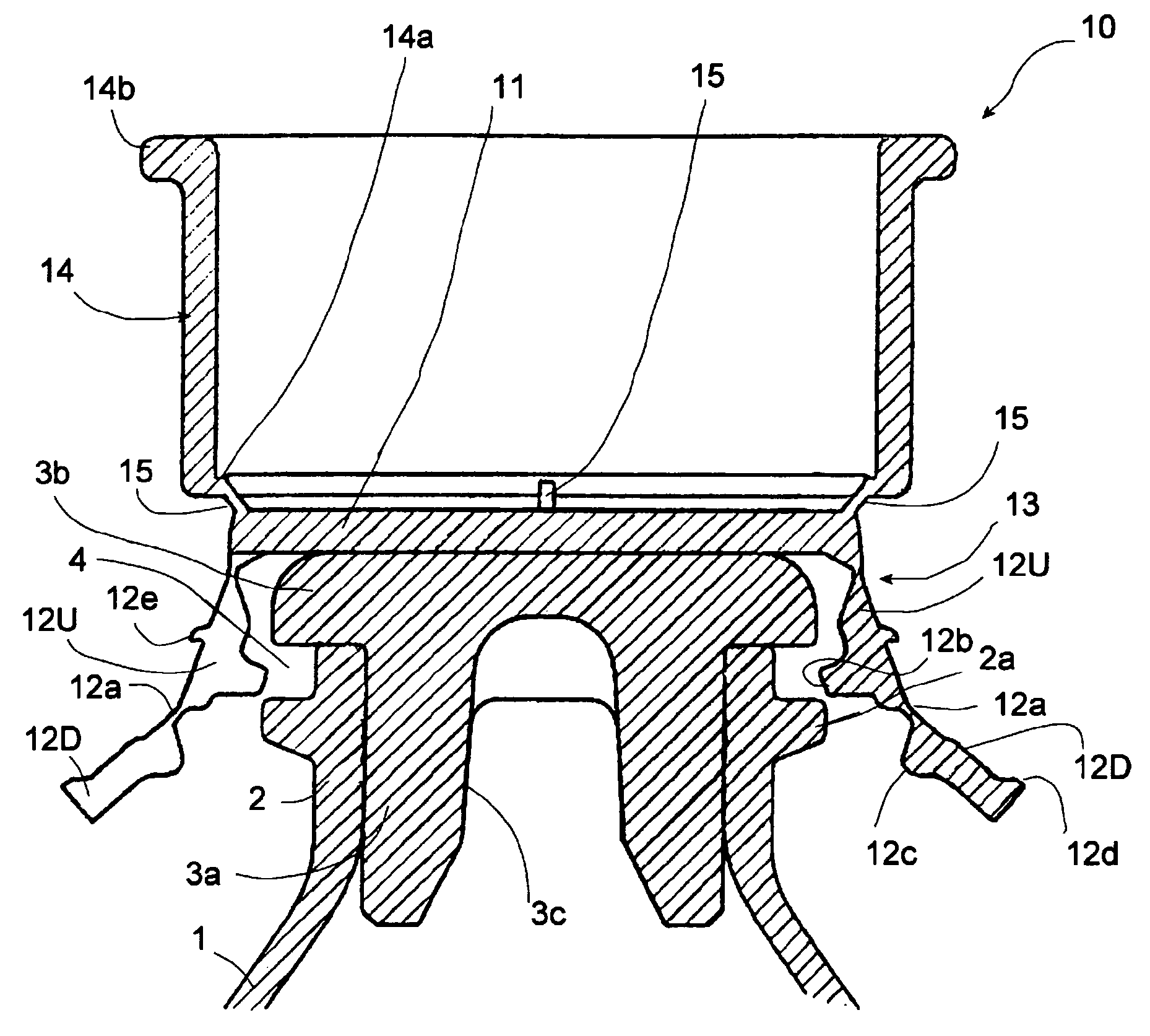
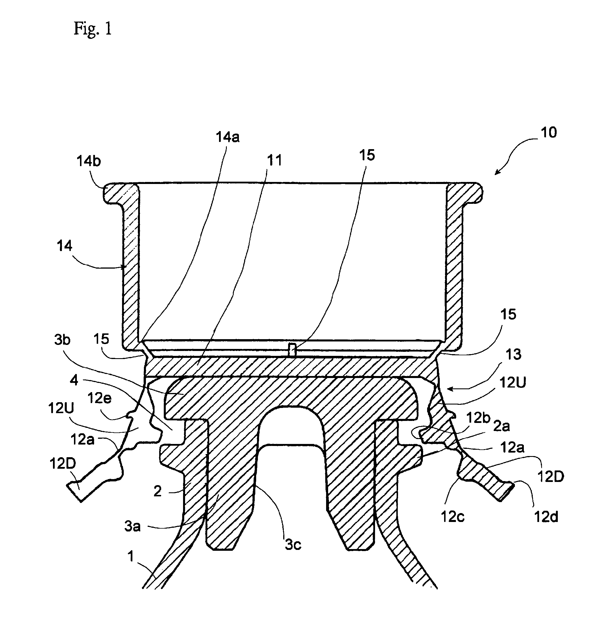
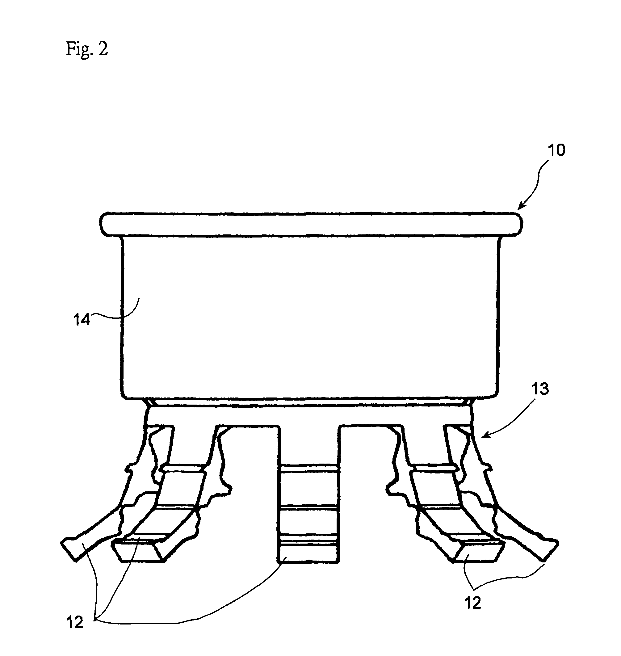
[0019]FIGS. 1 to 6 illustrate a collet plastic cap 10 according to the embodiment of the present invention. The cap 10 is fixed on an upper mouth 2 of a vial (a container) 1 and tops a rubber plug 3, which is fitted tightly into the mouth 2.

[0020]The vial 1 is a transparent glass container. The mouth 2 has a cylindrical shape, and a flange 2a projects from the outer periphery of the mouth 2. Between the upper edge surface of the mouth 2 and the flange 2a, there is a gap 4 extending toward upwards and downwards.

[0021]The rubber plug 3 comprises an airtight portion 3a put in the mouth 2 and a flange 3b, from which the airtight portion 3a depends and which makes contact with the upper edge surface of the mouth 2, as a single piece. The airtight portion 3a extends a significant distance into the mouth. The external diameter of the flange 3b is larger than th...


PUM

PropertyMeasurementUnit
external diameteraaaaaaaaaa
distanceaaaaaaaaaa
adhesionaaaaaaaaaa

Abstract

A container cap locking a plug member to a mouth by a locking member and capable of being removed from the mouth together with the plug member by repositioning a holder member. The locking member is covered on the container mouth so as to hold the plug and the holder member is fitted to the outer peripheral sides of a plurality of locking pieces of the locking member. In each locking piece, an upper side part is connected to a lower side part through a thin-walled bending part. The upper side part is locked to the rubber plug from the lower side with the holder member on the outer peripheral side thereof. The lower side part is locked to the container mouth from the lower side by the holder member. Locking projected parts prevent the lower end of the holder member from coming out of the upper side part.

Description

FIELD OF THE INVENTION[0001]The present invention relates to a container cap, which holds a plug member such as a rubber container plug firmly by being put on the mouth of the container sealed by the plug.BACKGROUND ART[0002]Conventional containers such as vials, which hold drugs, are sealed pathways to mouths with sufficiently sterilized rubber plugs in order to store and carry the drugs in hygienic conditions. They are provided with lock means to the rubber plugs around the mouths so as to prevent these rubber plugs from loosening up and the conditioner from deterioration caused by air inflow through a gap between the rubber plugs and the mouths.[0003]As with the lock means described above, the applicant of the present invention has disclosed the cap which comprises a close-fastening ring detachably formed on an upper portion of a crown-like member surrounding a rubber plug in the corresponding document 1. It is used in such a manner that the close-fastening ring is cut off from t...

Claims


Application Information

Patent Timeline
Patent Type & Authority Patents(United States)
IPC IPC(8): B65D41/62B65D51/22
CPCB65D39/16B65D41/28B65D51/20B65D51/243B65D2251/0028B65D2251/0075B65D45/322
Inventor HAMAMOTO, KEIJIYOSHIMURA, SEIJITAMAOKI, SHITOMI
Owner TAISEI KAKO CO LTD
Why Eureka
Try Eureka