Media feeding and width sensing methods and apparatus for printing systems

a technology of media feeding and width sensing, which is applied in the direction of transportation and packaging, thin material processing, article separation, etc., can solve the problems of limited resolution of these automated width measurement systems and difficulty in discriminating between standard media sizes, and achieve the effect of increasing the resolution capability of the media width sensing apparatus

Inactive Publication Date: 2010-12-07
XEROX CORP
View PDF13 Cites 31 Cited by
  • Summary
  • Abstract
  • Description
  • Claims
  • Application Information

AI Technical Summary

Benefits of technology

[0003]In one possible implementation, both media guides are movable along an axis in synchronism via a rack and pinion system and when pushed together, the guides centrally register the inserted media in the tray. The slider of the potentiometer is biased against a profile edge of a rack connected to the first media guide, and the rack provides the obstruction fin or fins to selectively open or close the optical signal path of the opto-interrupt sensor as the guide is moved, wherein the output signals of the potentiometer and the opto-interrupt sensor are used to determine the width of the inserted media. In certain examples, the profile of the ramp structure edge includes two or more profile portions to move the potentiometer slider in a first direction as the first media guide is moved in the first portion of the movement range and to move the slidable member in the opposite direction as the guide is moved in the second portion of the movement range, with the opto-interrupt sensor providing different Boolean output states to differentiate between the movement range portions. In this manner, the effective range of the potentiometer can be utilized twice or even more to increase the resolution capability of the media width sensing apparatus.

Problems solved by technology

However, the resolution of these automated width measurements systems is limited and is subject to mechanical and electrical tolerance variations, whereby discriminating between standard media sizes is often difficult and these systems typically require calibration procedures to ensure correct identification of the inserted media width.

Method used


Image

  • Media feeding and width sensing methods and apparatus for printing systems
  • Media feeding and width sensing methods and apparatus for printing systems
  • Media feeding and width sensing methods and apparatus for printing systems

Examples


Embodiment Construction

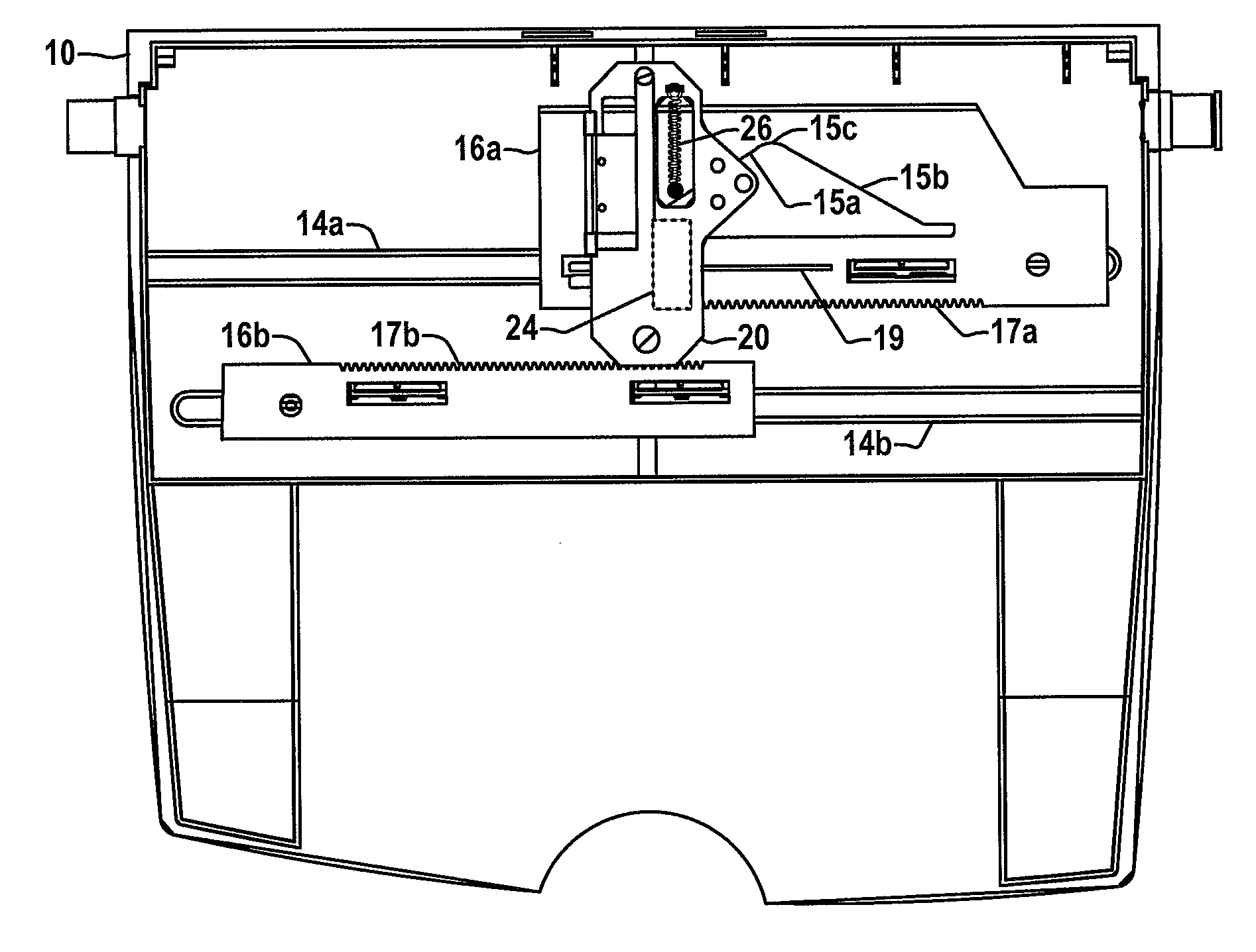
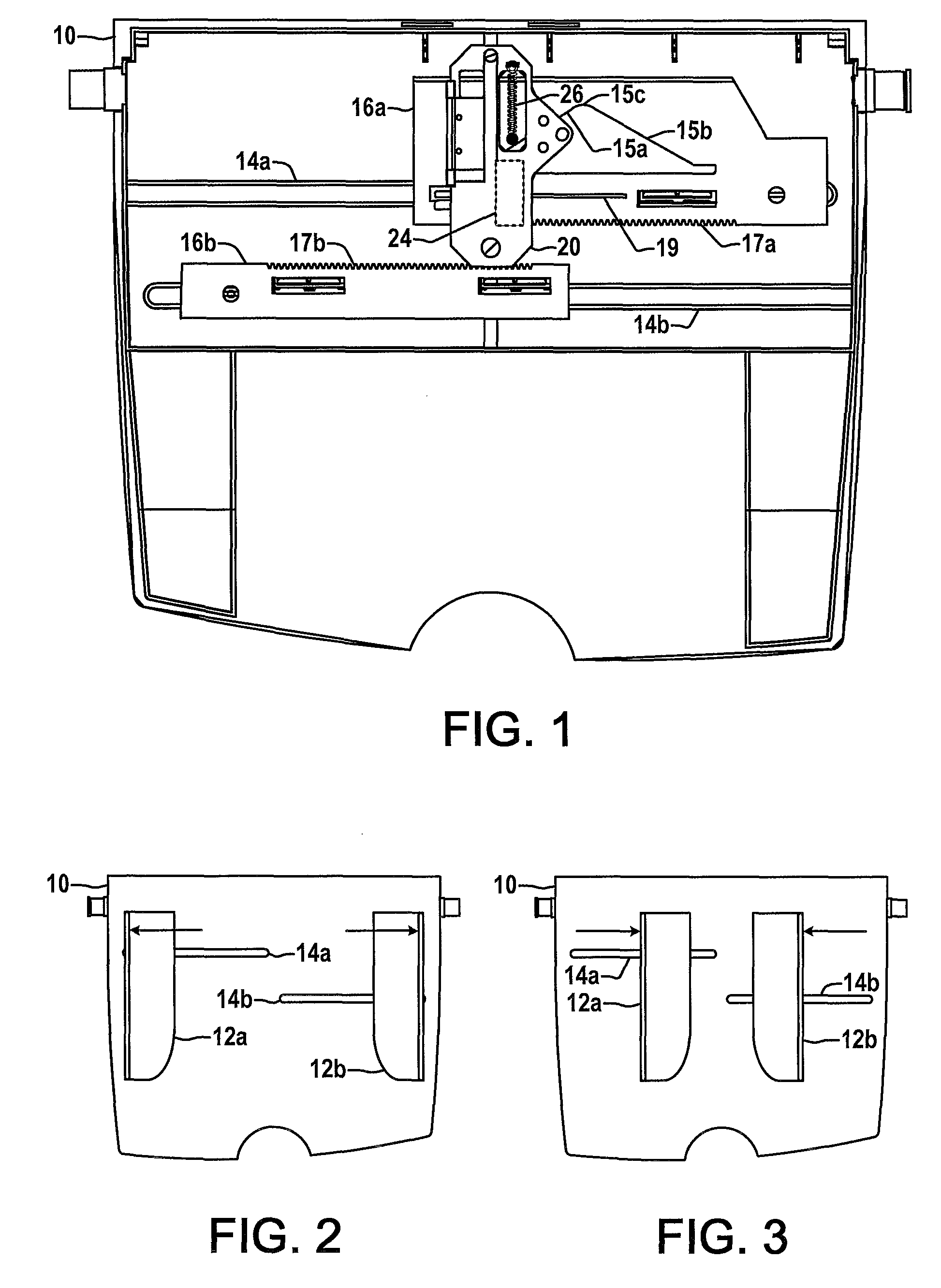
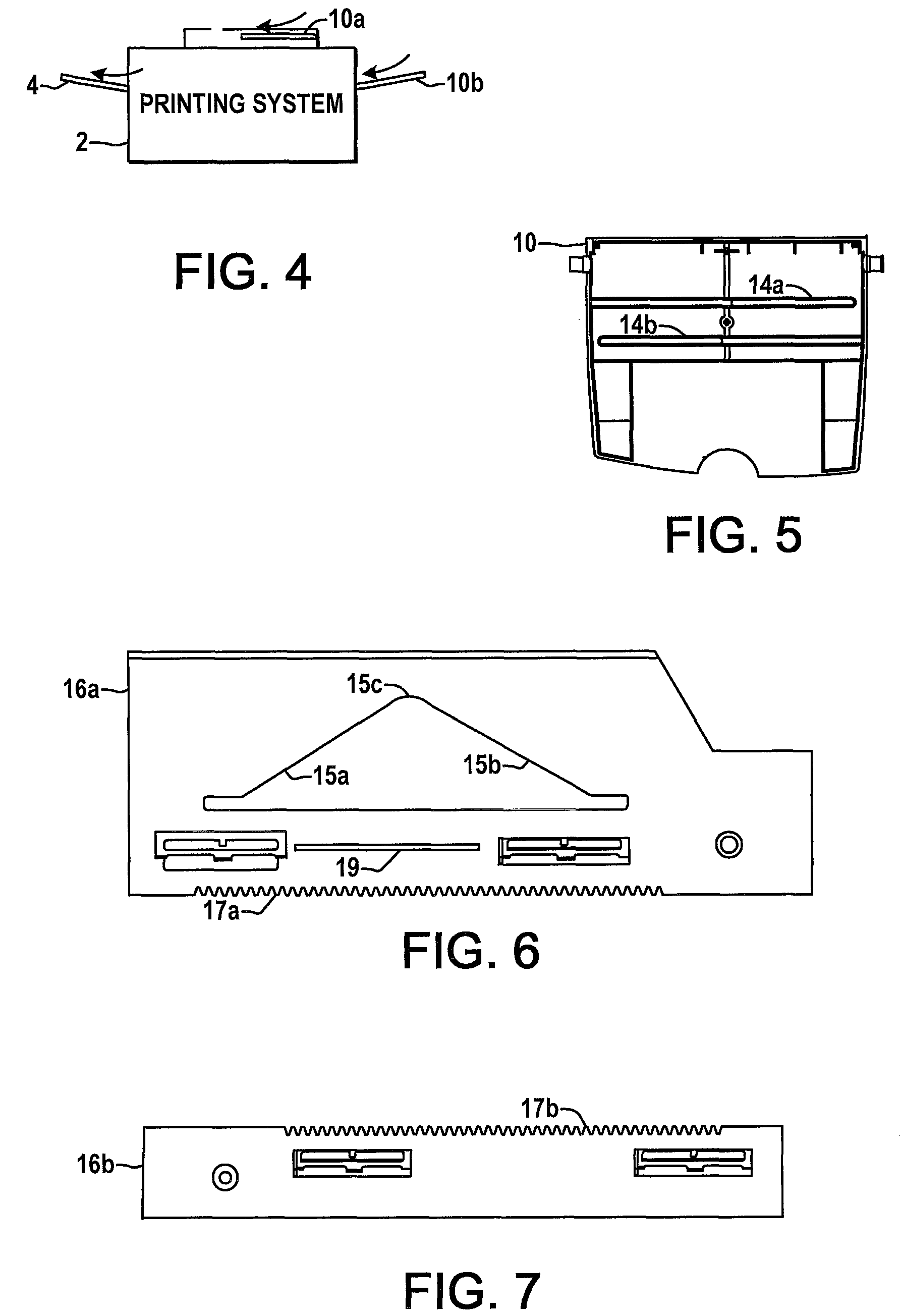
[0024]Referring now to the drawings, wherein the various structures and features are not necessarily drawn to scale, FIG. 4 depicts a printing machine or printing system 2 with an output tray 4 which receives printed media, as well as media feeding apparatus 10 for introducing media into the system 2. One feeding apparatus 10a operates to feed original media into the printing system 2 and a second apparatus 10b is a bypass tray for introducing printable media into the system 2. The printing system 2 can be any form of copier, printer, facsimile machine, or other system having one or more print engines or components by which visual images, graphics, text, etc., are printed on a page or other printable media, including xerographic, electro photographic, and other types of printing technology, wherein such components are not specifically illustrated to avoid obscuring the various media feeding and width determination features of the present disclosure. In general, the media feeders and...


PUM


Abstract

Systems and methods for feeding media into a printing system in which a movable media guide is used to register media on a tray with a potentiometer and an opto-interrupt sensor are mounted in a fixed position relative to the tray with the slidable potentiometer member being moved by translation of the media guide. An obstruction structure is coupled to move relative to the opto-interrupt sensor when the media guide is translated and provides one or more fins to selectively block or open the optical signal path of the opto-interrupt sensor, with the sensed media width being determined according to the output signals of the opto-interrupt sensor and the potentiometer.

Description

BACKGROUND[0001]Printing systems such as copiers, printers, facsimile devices or other systems having a print engine for creating visual images, graphics, texts, etc. on a page or other printable medium typically include various feeding systems for introducing original image media or printable media into the system. Examples include document feeders into or onto which a user inserts original documents from which images are obtained, as well as so-called bypass trays for introducing printable media into a printing system. These media feeders typically include media guide structures with which the inserted media is registered by moving one or both of the guides to engage opposite sides of the media, thereby fixing the location of the media relative to the entry path into the system. Advanced printing systems often provide for automatic or semi-automatic identification of the width of the inserted media according to the relative location of the media guides, and use the size informatio...

Claims


Application Information

Patent Timeline
Patent Type & Authority Patents(United States)
IPC IPC(8): B65H1/00
CPCB65H1/04B65H2511/12B65H2511/51B65H2553/21B65H2553/41B65H2220/04B65H2220/11B65H2220/03
Inventor WINDSOR, MICHAEL ROSSBRIDGES, RICHARD T. C.
Owner XEROX CORP
Why Eureka
Try Eureka