
Printer with zero insertion force printhead cartridge

a technology of inkjet printer and cartridge, which is applied in the field of printers, can solve the problems of inability to eject ink from individual nozzles, high print speed requires a large ink supply flow rate, and the ink supply of the entire length of the pagewidth printhead is more complex

Active Publication Date: 2010-12-07
MEMJET TECH LTD +1
View PDF5 Cites 18 Cited by
  • Summary
  • Abstract
  • Description
  • Claims
  • Application Information

AI Technical Summary

Benefits of technology

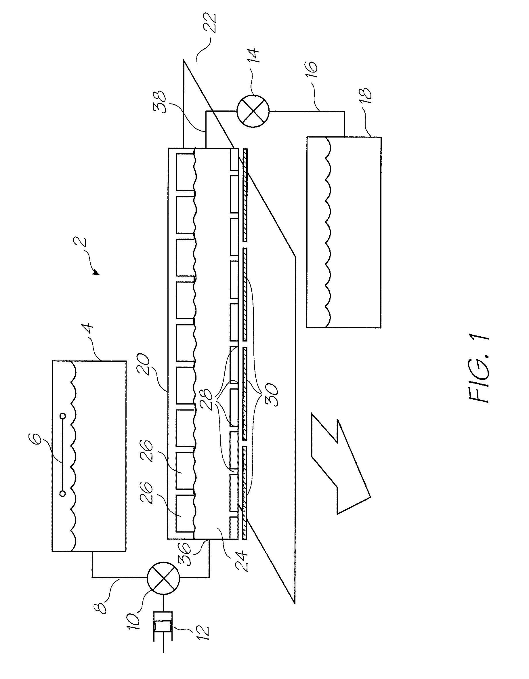
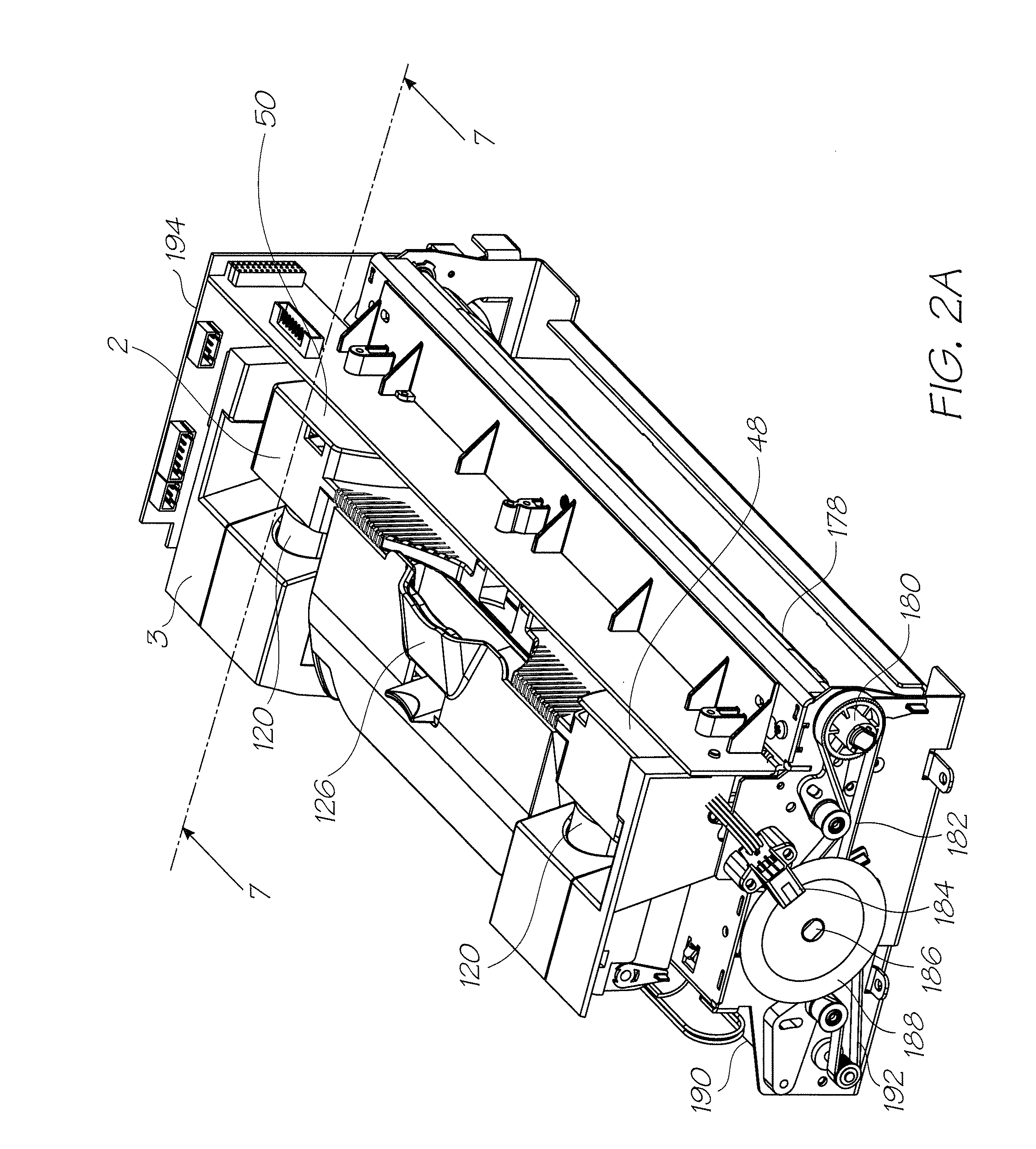
[0016]The linking the operation of the latch mechanism to the fluid coupling between the ink reservoir and the printhead cartridge, the sealed fluid connection is formed with the assistance of mechanical advantage. The latch can be configured so that the coupling between the printhead and the ink supply is in essence the zero insertion force coupling. Furthermore with the fluid connection made while the printhead cartridge is supported by the cradle, the cartridge structure is not subjected to damaging stresses.

Problems solved by technology

The high print speeds require a large ink supply flow rate.
Not only are the flow rates higher but distributing the ink along the entire length of a pagewidth printhead is more complex than feeding ink to a relatively small reciprocating printhead.
This recognises that individual ink ejection nozzles may fail over time and eventually there are enough dead nozzles to cause artefacts in the printed image.
The supply flowrate to the pagewidth printhead is too high for needle valves because of the narrow internal diameter.
It is also structurally undesirable to subject the cartridge to large forces.

Method used


Image

  • Printer with zero insertion force printhead cartridge
  • Printer with zero insertion force printhead cartridge
  • Printer with zero insertion force printhead cartridge

Examples


first embodiment

[0126]FIG. 26 shows the inclusion of the wiper blade cleaning pad 152. As with the first embodiment described above, the cleaning pad 152 is mounted in the printer so that the wiper blades 268 move across the surface of the pad 152 as the maintenance carousel 150 is rotated. By positioning the cleaning pad 152 such that the chassis 236 needs to be retracted from the printhead ICs 30 in order to allow the wiper blades 268 to contact pad, the chassis 236 can be rotated at relatively high speeds for a comprehensive clean of the wiper blades 268 while not risking any damaging contact with the printhead ICs 30. Furthermore the cleaning pad 152 can be wetted with a surfactant to better remove contaminants from the wiper blades surface.

[0127]FIG. 27 shows the injection molded chassis 236 in isolation. The chassis is symmetrical about two planes extending through the central longitudinal axis 282. This symmetry is important because an injection molded chassis extending the length of pagewid...

embodiment00

Five Maintenance Station Embodiment00

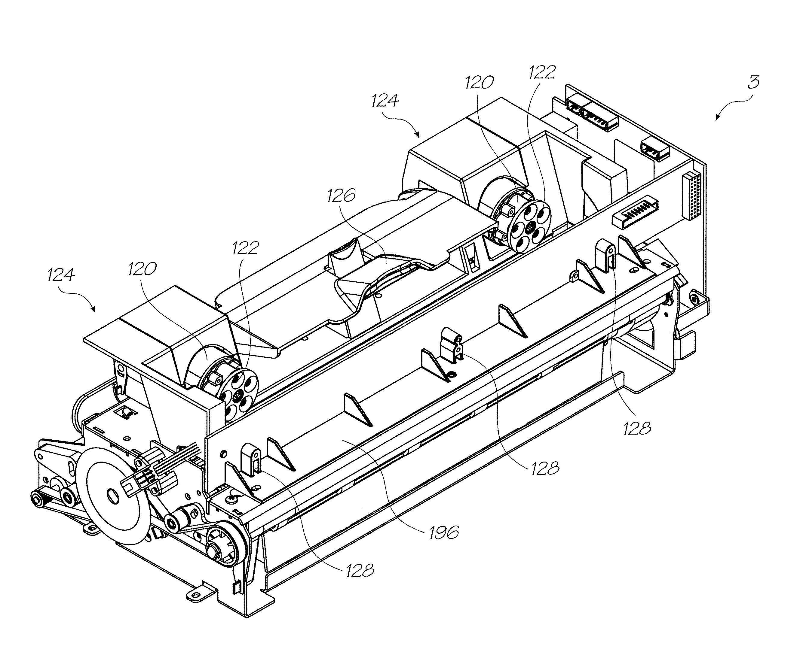
[0130]FIG. 34 shows an embodiment of the printhead maintenance carousel 150 with five different maintenance stations: a print platen 206, a printhead wiper 266, a printhead capper 272, a priming station 262 and a spittoon 284. The spittoon 284 (shown in isolation in FIG. 33) has a relatively simple structure—the spittoon face 284 presents flat to the printhead and has apertures (not shown) for fluid communication with the fibrous element 250 retained in its hard plastic base.

[0131]The five station maintenance carousel 150 adds a spittoon 284 to allow the printer to use major ink purges as part of the maintenance regime. The four station carousel of FIGS. 22-25, will accommodate minor ink purges or ‘spitting cycles’ using the print platen 206 and or the capper 272. A minor spitting cycle is used after a nozzle face wipe or as an inter-page spit during a print job to keep the nozzles wet. However, in the event that the printhead needs to be recover...


PUM


Abstract

An inkjet printer that has a printhead cartridge with a pagewidth printhead defining an array of nozzles for ejecting ink onto a media substrate. The printhead cartridge has a fluid coupling in fluid communication with the array of nozzles. The printer also has a cradle for supporting the printhead cartridge such that the array of nozzles is adjacent a media feed path extending through the printer, the cradle having a latch mechanism for retaining the printhead cartridge, an ink reservoir for containing supply of ink and a complementary coupling for fluid communication with the ink reservoir. The fluid coupling and the complementary coupling are configured to establish a sealed fluid connection using mechanical advantage provided by user actuation of the latch mechanism to retain the printhead cartridge in the cradle.

Description

FIELD OF THE INVENTION[0001]The present invention relates to be field of printers and in particular pagewidth inkjet printers.CO-PENDING APPLICATIONS[0002]The following applications have been filed by the Applicant simultaneously with the present application:[0003]12 / 014,76712 / 014,76812 / 014,76912 / 014,77012 / 014,77112 / 014,77212 / 014,77312 / 014,77412 / 014,77512 / 014,77612 / 014,77712 / 014,77812 / 014,77912 / 014,78012 / 014,78112 / 014,78212 / 014,78312 / 014,78412 / 014,78512 / 014,78712 / 014,78812 / 014,78912 / 014,79112 / 014,79212 / 014,79312 / 014,79412 / 014,79612 / 014,79812 / 014,80112 / 014,80312 / 014,80412 / 014,80512 / 014,80612 / 014,807[0004]The disclosures of these co-pending applications are incorporated herein by reference.CROSS REFERENCES[0005]The following patents or patent applications filed by the applicant or assignee of the present invention are hereby incorporated by cross-reference.[0006]6,276,8506,520,6316,158,9076,539,1806,270,1776,405,0556,628,4306,835,1356,626,5296,981,7697,125,3387,125,3377,136,1867,286,2...

Claims


Application Information

Patent Timeline
Patent Type & Authority Patents(United States)
IPC IPC(8): B41J2/175B41J2/17B41J2/155
CPCB41J2/175B41J2/17509B41J2/17513B41J2/17553B41J29/02
Inventor HIBBARD, CHRISTOPHERMACKEY, PAUL IANDYER, GEOFFREY PHILIPBERTOK, ATTILASILVERBROOK, KIA
Owner MEMJET TECH LTD
Learn More