Driving controlling apparatus for linear compressor and method thereof

a linear compressor and control apparatus technology, applied in the direction of motor/generator/converter stopper, dynamo-electric converter control, piston pump, etc., can solve the problems of stroke tremble phenomenon and difficulty in executing stroke variation, and achieve the effect of stably varying

Inactive Publication Date: 2010-12-07
LG ELECTRONICS INC
View PDF6 Cites 281 Cited by
  • Summary
  • Abstract
  • Description
  • Claims
  • Application Information

AI Technical Summary

Benefits of technology

[0019]Therefore, an object of the present invention is to provide a driving controlling apparatus for a linear compressor capable of stably varying a stroke in a large cooling capacity condition by judging a load state according to a phase difference between a current and a stroke, then by implementing a voltage control mode at the time of an overload (more than a TDC), and by implementing a current control mode at the time of a normal load (less than the TDC), and a method thereof.
[0020]To achieve these and other advantages and in accordance with the purpose of the present invention, as embodied and broadly described herein, there is provided a driving controlling apparatus for a linear compressor, comprising: a storing unit for storing a reference phase difference to judge an overload state; and a controlling unit for judging an overload state based on a comparison result between the reference phase difference and a phase difference between a current and a stroke, and controlling a voltage or a current applied to a linear motor based on the judgement result.
[0022]To achieve these and other advantages and in accordance with the purpose of the present invention, as embodied and broadly described herein, there is also provided a driving controlling apparatus for a linear compressor driven with a constant stroke command value, the method comprising: detecting a voltage or a current applied to a linear motor thereby calculating a stroke; detecting a phase difference between the calculated stroke and a current; and comparing the detected phase difference with a reference phase difference, selecting a voltage control mode or a current control mode based on the comparison result, and thereby driving the linear motor.

Problems solved by technology

However, as shown in FIG. 3, when a voltage control is performed in the linear compressor with a removed capacitor, the voltage applied to the linear compressor is not proportional to the stroke but a stroke tremble phenomenon occurs.
Accordingly, it is difficult to perform the stroke variation.

Method used


Image

  • Driving controlling apparatus for linear compressor and method thereof
  • Driving controlling apparatus for linear compressor and method thereof
  • Driving controlling apparatus for linear compressor and method thereof

Examples


Embodiment Construction

[0031]Reference will now be made in detail to the preferred embodiments of the present invention, examples of which are illustrated in the accompanying drawings.

[0032]Hereinafter, will be explained a driving controlling apparatus for a linear compressor capable of stably varying a stroke in a large cooling capacity condition by judging a load state according to a phase difference between a current and a stroke, then by implementing a voltage control mode at the time of an overload (more than a TDC), and by implementing a current control mode at the time of a normal load (less than the TDC), and a method thereof.

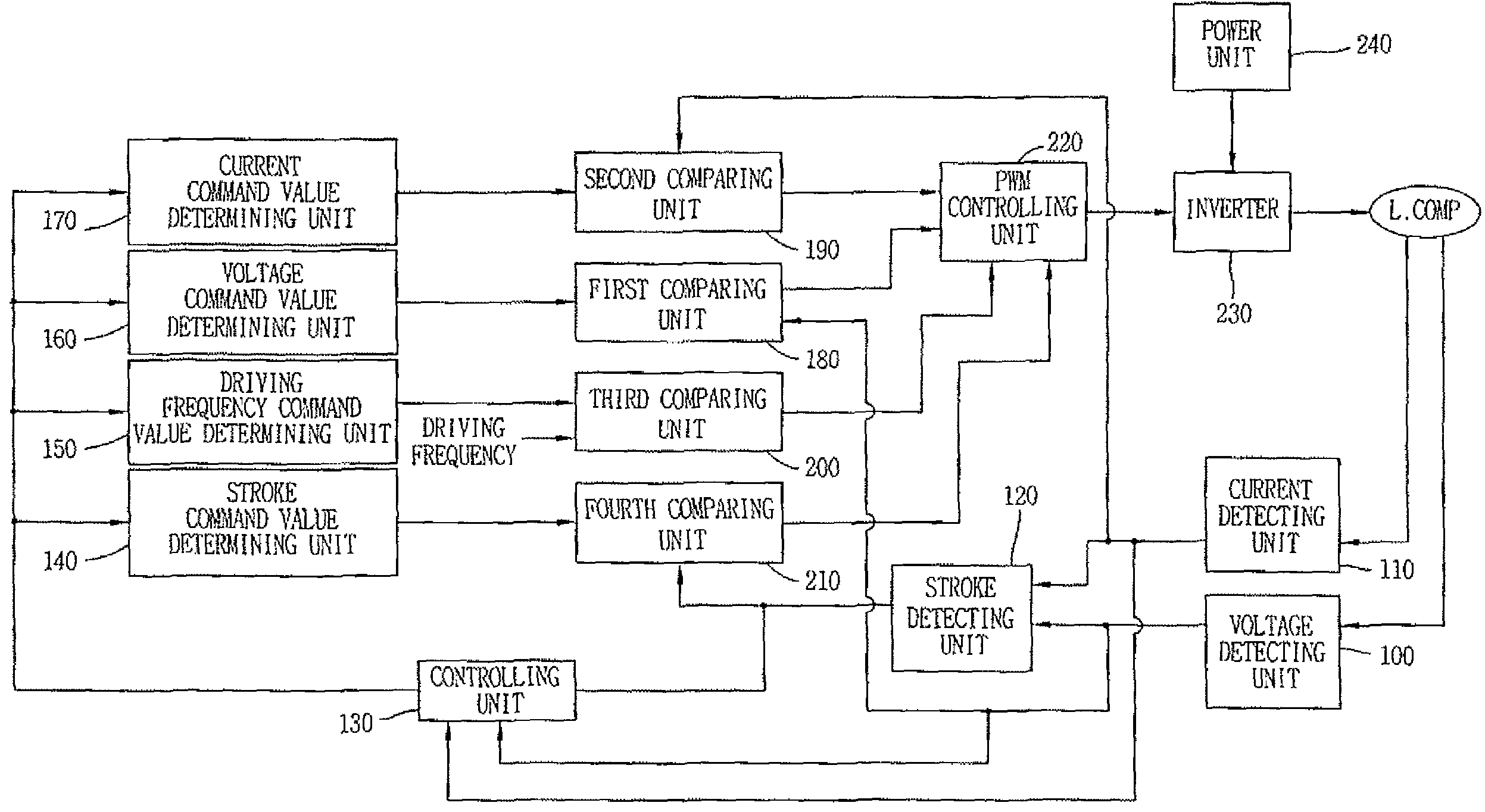
[0033]FIG. 4 is a block diagram showing a driving controlling apparatus for a linear compressor according to the present invention.

[0034]As shown in FIG. 4, the driving controlling apparatus for a linear compressor according to the present invention comprises a voltage detecting unit 100, a current detecting unit 110, a stroke detecting unit 120, a controlling unit 130, a fir...


PUM


Abstract

A driving controlling apparatus for a linear compressor, comprises: a storing unit for storing a reference phase difference to judge an overload state; and a controlling unit for judging an overload state based on a comparison result between the reference phase difference and a phase difference between a current and a stroke, and controlling a voltage or a current applied to a linear motor based on the judgement result.

Description

RELATED APPLICATION[0001]The present disclosure relates to subject matter contained in priority Korean Application No. 10-2006-0033778, filed on Apr. 13, 2006, which is herein expressly incorporated by reference in its entirety.BACKGROUND OF THE INVENTION[0002]1. Field of the Invention[0003]The present invention relates to a linear compressor, and more particularly, to a driving controlling apparatus for a linear compressor capable of stably varying a stroke in a large cooling capacity condition by implementing a voltage control mode at the time of an overload (more than a TDC), and by implementing a current control mode at the time of a normal load (less than the TDC), and a method thereof.[0004]2. Description of the Background Art[0005]Generally, a linear compressor reciprocates a piston with using a linear motion of a motor by directly connecting the piston to a mover of a linear motor.[0006]When the linear compressor is applied to a compressor or a refrigerator a compression rat...

Claims


Application Information

Patent Timeline
Patent Type & Authority Patents(United States)
IPC IPC(8): F04B49/06F04B35/04H02K33/00
CPCF04B35/045H02P25/027H02P25/06H02P29/027F04B2203/0401F04B2203/0402H02P25/032H02P29/02H02P2209/09Y10S388/912
Inventor SUNG, JI-WOONYOO, JAE-YOOLEE, CHEL-WOONG
Owner LG ELECTRONICS INC
Why Eureka
Try Eureka