Exposure control method and imaging apparatus

a control method and imaging technology, applied in the field of exposure control methods and imaging apparatuses, can solve problems such as bridging out background and improper exposure of obtained images

Inactive Publication Date: 2010-12-07
FUJIFILM CORP
View PDF11 Cites 4 Cited by
  • Summary
  • Abstract
  • Description
  • Claims
  • Application Information

AI Technical Summary

Benefits of technology

[0011]In view of the foregoing, a primary object of the present invention is to provide an exposure control method and an imaging apparatus, which make it possible to emit a flash light properly in the low brightness backlit scene.
[0017]When the calculated proper exposure value is not less than the threshold exposure value, the scene is not judged to be the low brightness backlit scene. Since the different rear light threshold value is applied to the judgment for the low brightness backlit scene from that applied to the ordinary rear light judgment, a risk of flashing to a front-lit scene at a high imaging sensitivity is eliminated, and thus the obtained image is prevented from being over-exposed and bleached out.

Problems solved by technology

However, as the low brightness flashing point is set at the lower value, i.e. EV5, in the digital camera with the sensitivity changing function, if the low brightness backlit scene is so dark that its exposure value is EV8 to EV5, the scene is shot without the flash in this type digital camera, so the obtained image is improperly exposed.
If, however, the subject distance is so far that the flash light does not reach the subject, the image processing can result in breaching out the background.

Method used


Image

  • Exposure control method and imaging apparatus
  • Exposure control method and imaging apparatus
  • Exposure control method and imaging apparatus

Examples


Embodiment Construction

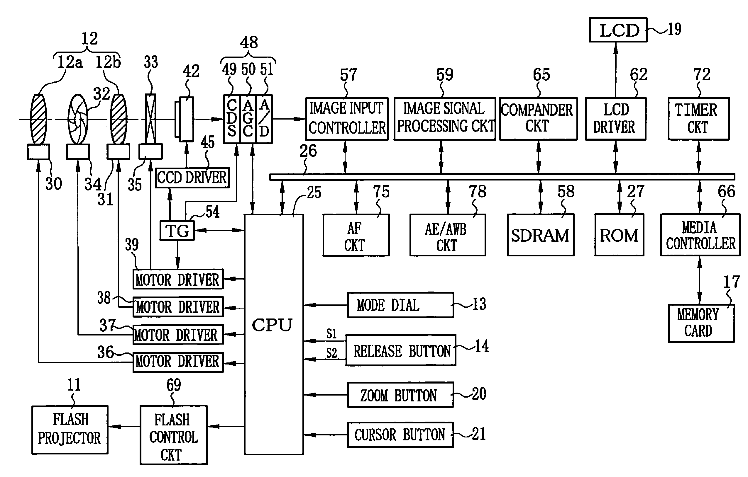
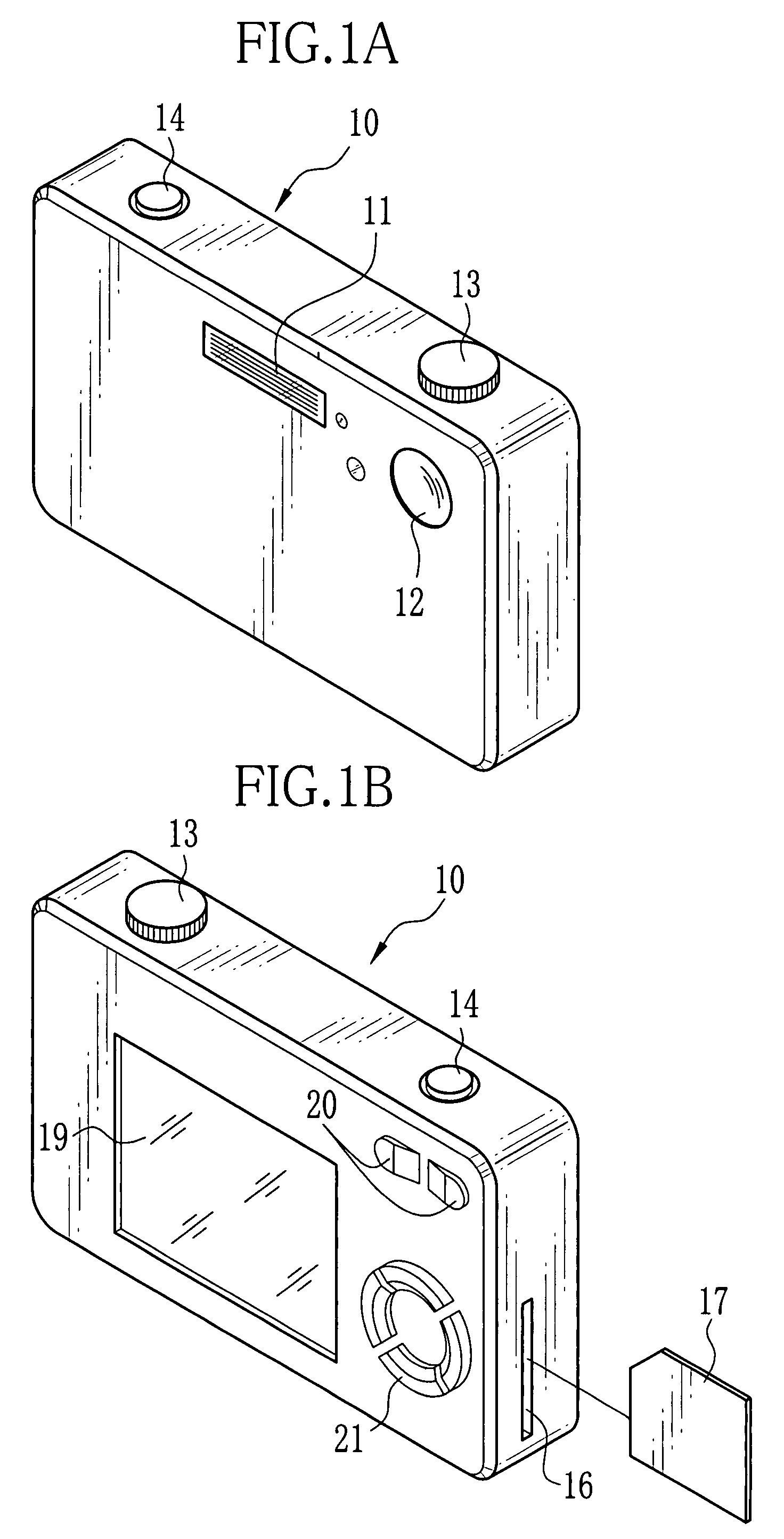
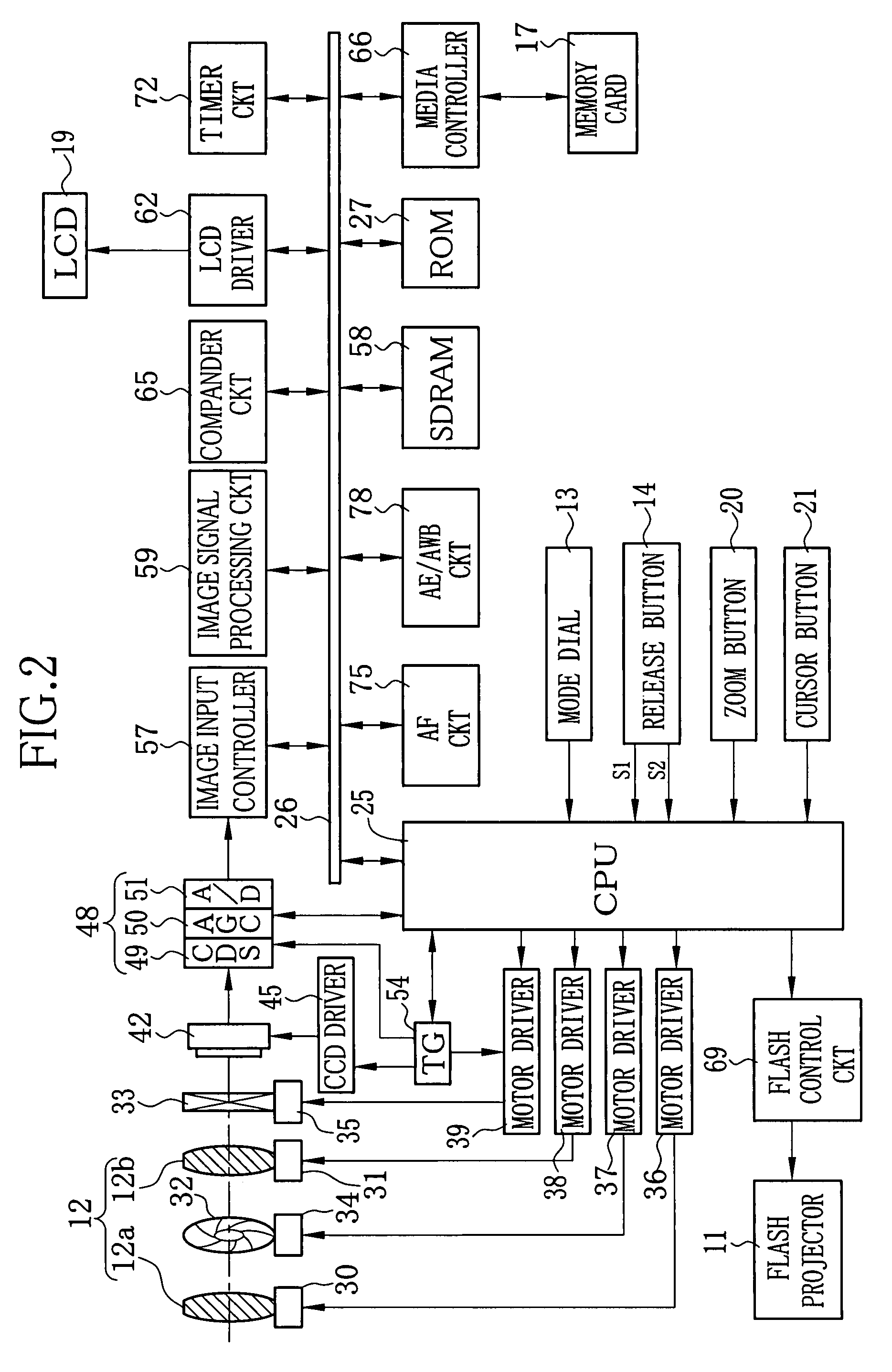
[0036]As shown in FIGS. 1A and 1B, a digital camera 10 embodying an imaging apparatus of the present invention has a thin substantially parallelepiped body. A flash projector 11 for projecting a flash light toward a subject, and a taking lens 12 for forming an optical image of the subject are disposed on a front of the digital camera 10. A mode dial 13 and a release button 14 are disposed on a top of the digital camera 10.

[0037]The mode dial 13 is turned to switch over between indexed positions. When the mode dial 13 is turned from a power-off position to one of other positions for selecting various modes, including a still image shooting mode, a moving image shooting mode, a reproduction mode and a setup mode, the digital camera 10 is powered on. The release button 14 can be pressed in two steps, that is, to a half-pressed position and a full-pressed position. As will be described in detail later, when the release button 14 is operated into the half-pressed position, a first switch...


PUM


Abstract

A digital camera automatically changes its imaging sensitivity based on a proper exposure value that is calculated at a predetermined standard imaging sensitivity based on subject brightness measured from a photometry area of a scene to shoot. When the decided imaging sensitivity is higher than a predetermined sensitivity threshold value, the scene is judged to be a low brightness backlit scene that contains a higher brightness portion around a dark main subject, and a lower brightness portion around the higher brightness portion. A rear light judgment value is calculated as a difference between a central photometric value and a peripheral photometric value of a photometry area, and is compared with a predetermined rear light threshold value, to judge whether the scene is backlit or not. When the scene is judged to be a backlit scene or a low brightness backlit scene, the digital camera emits a flash light synchronously with an exposure.

Description

FIELD OF THE INVENTION[0001]The present invention relates to an exposure control method and an imaging apparatus, and more particularly to an imaging apparatus that has a function to change imaging sensitivity and a function to emit a flash light to a backlit scene.BACKGROUND OF THE INVENTION[0002]Digital cameras have been widespread, which convert an optical image of a subject into electric image signal through an imaging device, such as a CCD image sensor or a CMOS image sensor. The image signal is converted into digital image data, and is written in a memory or a recording medium. Many of the digital cameras are provided with a flash device for projecting a flash of illumination light to the subject during an exposure, some of which automatically emit the flash light according to the subject brightness in an automatic flash mode.[0003]FIG. 11 shows an example of a program chart used for an automatic exposure control operation in a conventional digital camera, wherein a horizontal...

Claims


Application Information

Patent Timeline
Patent Type & Authority Patents(United States)
IPC IPC(8): H04N5/222
CPCG03B15/03
Inventor KOBAYASHI, KOJI
Owner FUJIFILM CORP
Why Eureka
Try Eureka