

Light source apparatus, method for controlling light source apparatus, and display apparatus
a technology for light source apparatuses and light sources, which is applied in the direction of lighting and heating apparatuses, instruments, static indicating devices, etc., can solve the problem that the emission brightness of emission units cannot be adjusted very accurately, and achieve the effect of very accurate adjustmen
- Summary
- Abstract
- Description
- Claims
- Application Information
AI Technical Summary
Benefits of technology
Problems solved by technology
Method used
Image

Examples
embodiment 1
[0065]A light source apparatus and a control method thereof according to Embodiment 1 of the present invention will now be described. This embodiment shows a case when the light source apparatus is a backlight apparatus which is used for a color image display apparatus, but the light source apparatus is not limited to a backlight apparatus used for a display apparatus. The light source apparatus may be such a light apparatus as a street light and an indoor light.
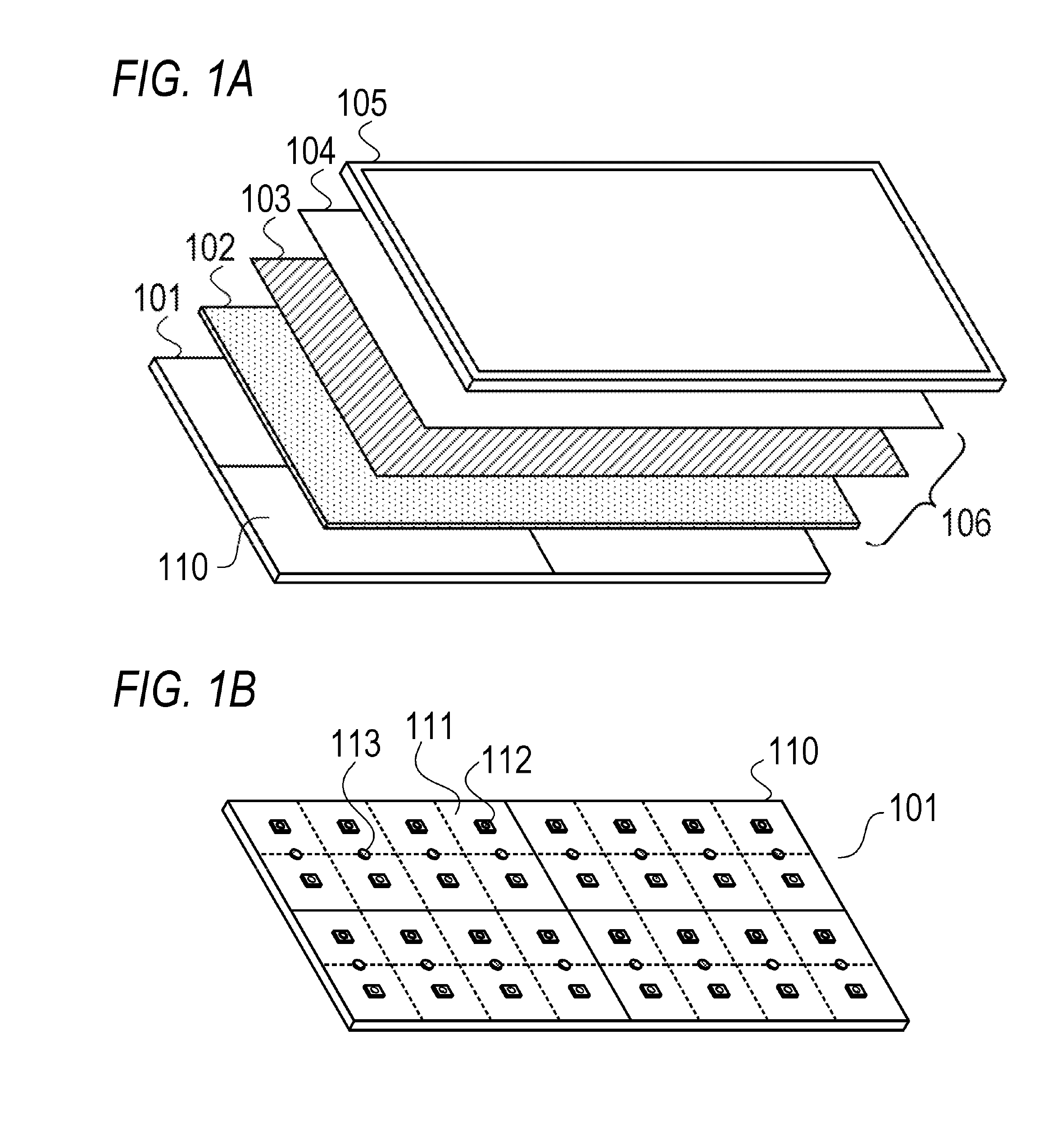
[0066]FIG. 1A is a schematic diagram depicting an example of a configuration of a color image display apparatus according to this embodiment. The color image display apparatus has a backlight apparatus and a color liquid crystal panel 105. The backlight apparatus includes a light source substrate 101, a diffuser plate 102, a light collecting sheet 103, and a reflection type polarizing film 104.
[0067]The light source substrate 101 emits light (white light) which is irradiated onto the back face of the color liquid crystal pan...
embodiment 2
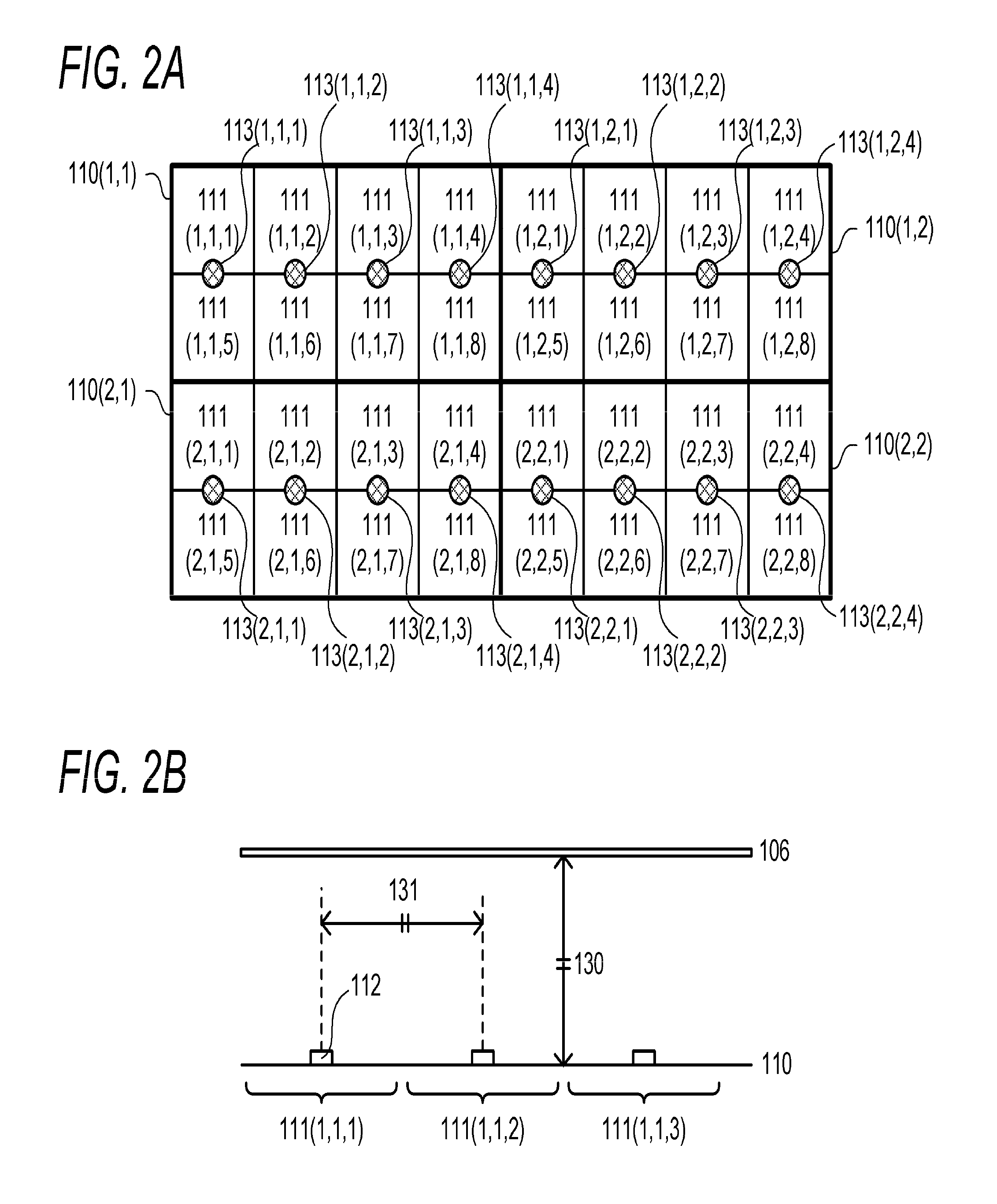
[0135]A light source apparatus according to Embodiment 2 of the present invention will now be described. In Embodiment 1, a case when one light source (LED chip 112) is located to one emission unit 111 and the LED pitch 131 and the diffusion distance 130 are the same was described. In this embodiment, a case when a plurality of light sources (a plurality of LED chips 112) is disposed in one emission unit 111, and the LED pitch 131 and the diffusion distance 130 are not the same will be described. A composing element the same as Embodiment 1 is denoted with a same reference numeral for which description is omitted.
[0136]In Embodiment 1, one LED chip 112 is disposed in one emission unit 111, but a total of 4 LED chips 112 (2 rows×2 columns) or a total of 9 LED chips 112 (3 rows×3 columns), for example, may be disposed in one emission unit 111.
[0137]FIG. 14A is a schematic diagram depicting an example when a total of 4 LED chips 112 (2 rows×2 columns) are disposed in one emission unit ...
embodiment 3
[0156]A light source apparatus according to Embodiment 3 of the present invention will now be described. In Embodiment 1 and Embodiment 2, a configuration of using an optical sensor, which is disposed in a position that faces a position on the back face of the optical sheet 106 where fluctuation of the brightness due to deflection of the optical sheet 106 is sufficiently small, was described. However if such an optical sensor is used for all the emission units 111, the number of optical sensors 113 increases and the manufacturing cost increases. In this embodiment, a configuration which allows decreasing brightness unevenness of the light source apparatus using a small number of optical sensors 113 will be described. A composing element the same as Embodiment 1 or Embodiment is denoted with a same reference numeral, for which description is omitted.
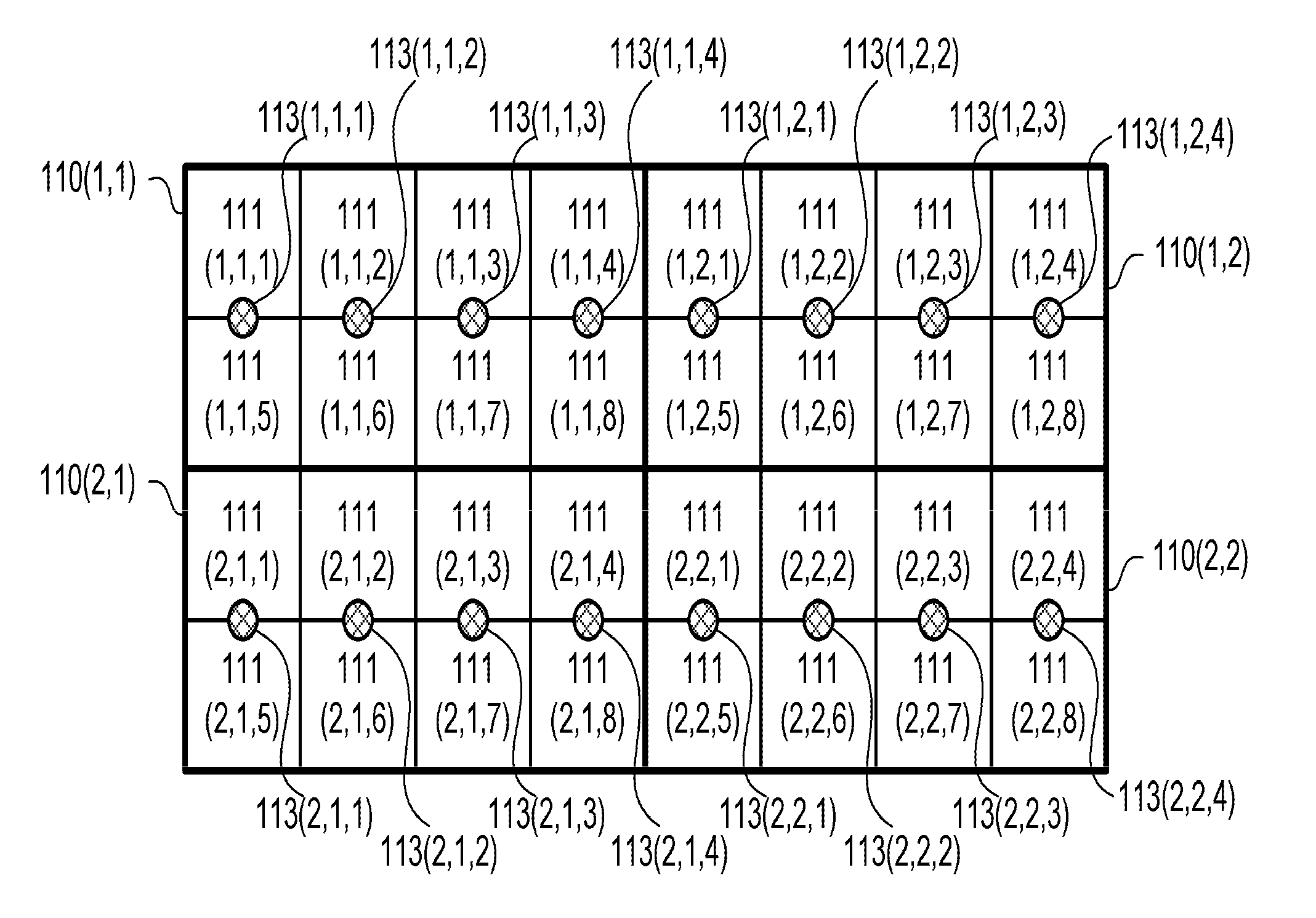
[0157]FIG. 19A is a schematic diagram depicting an example of a configuration of an LED substrate 110 according to this embodiment. In F...
PUM
| Property | Measurement | Unit |
|---|---|---|
| thickness | aaaaa | aaaaa |
| length | aaaaa | aaaaa |
| length | aaaaa | aaaaa |
Abstract
Description
Claims
Application Information