Al technical title is built by PatSnap Al team. It summarizes the technical point description of the patent document.
a technology of switching device and container, which is applied in the direction of charging, lighting and heating apparatus, furniture, etc., can solve the problems of inability to achieve high routing rate for containers routed using this device, complicated embodiment, and bulky implementation
Inactive Publication Date: 2010-12-14
SIDEL PARTICIPATIONS SAS
View PDF21 Cites 23 Cited by
Summary
Abstract
Description
Claims
Application Information
AI Technical Summary
This helps you quickly interpret patents by identifying the three key elements:
Problems solved by technology
Method used
Benefits of technology
[0010]According to this embodiment, it is thus possible to obtain a container routing rate that is higher than can be achieved with devices of the prior art while at the same time limiting the volume occupied by the means for retracting the retractable-cam section.
[0011]In order to produce a more compact routing device with a cam runway inside the plate in which the runway is formed rather than on the periphery of a fixed transverse plate, the retractable removable section is able at least partially to fill an opening in the fixed transverse plate.
[0023]Advantageously, each gripping arm comprises stop means able to limit the sliding of the gripping arm.
Problems solved by technology
The high throughputs of the latest-generation blow-molding machines no longer allow effective use of this picker, because the actuating cylinder does not have a swift enough response time.
However, this embodiment is unable to achieve high routing rates for the containers routed using this device.
However, this embodiment is relatively complicated and bulky to implement, particularly in terms of the means for retracting the retractable cam.
Method used
Image
Click on the blue label to locate the original text in one second.
Reading with bidirectional positioning of images and text.
Examples
Embodiment Construction
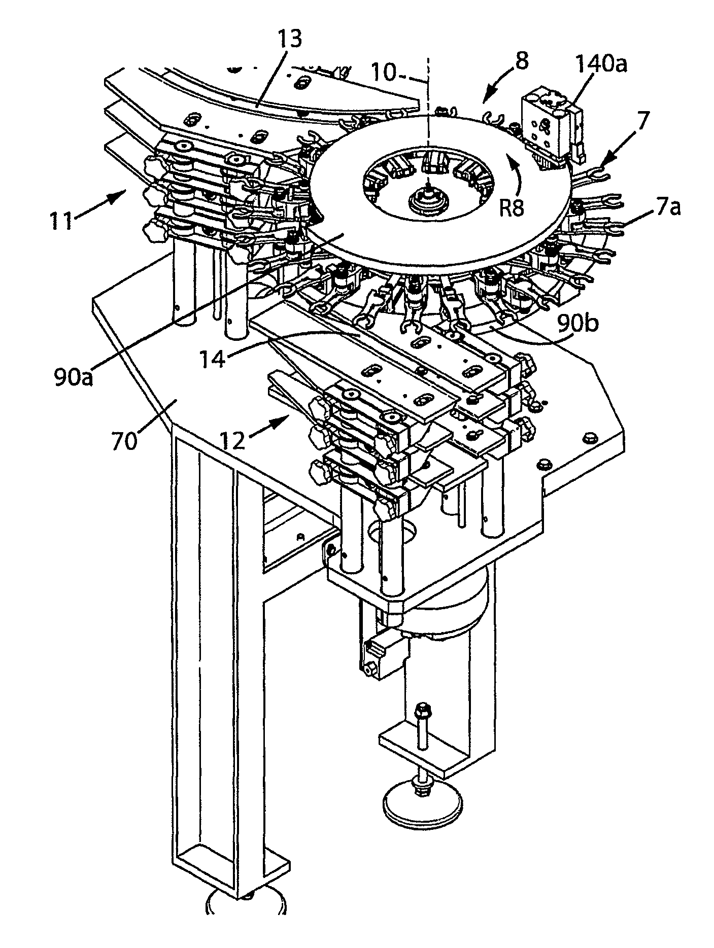
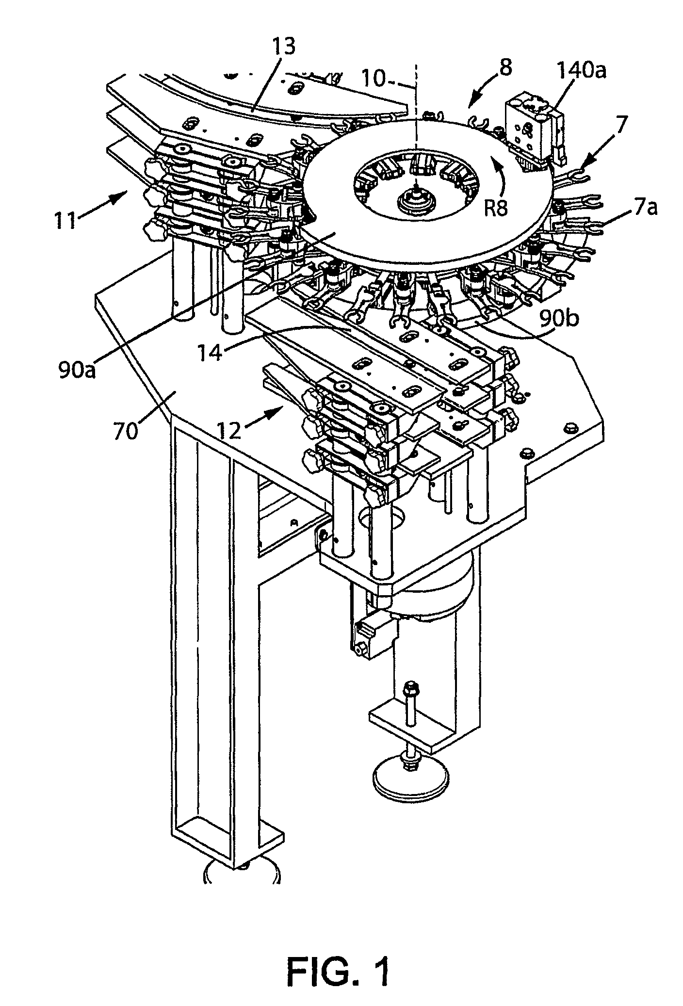
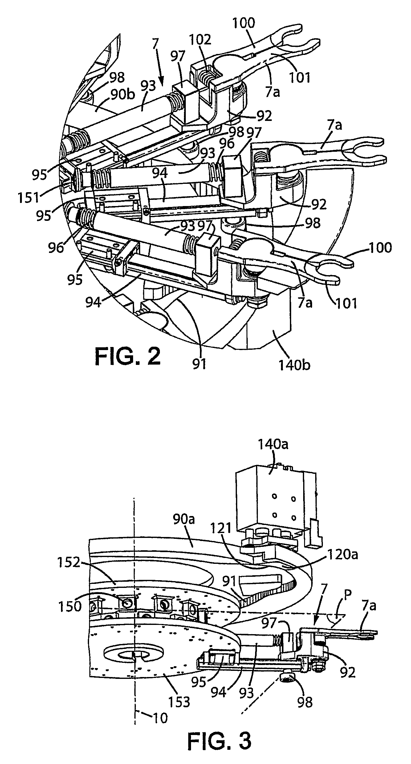
[0034]The present invention relates to a routing device 1 for switching containers, rotating about a fixed axis of rotation 10 and comprising a number of gripping arms 7 for gripping at least one container, the arms being provided at the periphery about the axis of rotation 10.
[0035]The device 1 according to the invention is in the form of a routing wheel 8 preferably allowing some of the containers to be ejected to a scrapping area or testing area. The routing wheel 8 allows containers of the bottle type to be conveyed to at least two outlets 11, 12 each comprising a guide lane 13, 14, means for altering the path of the gripping arms 7 of the routing wheel 8 in order to position these gripping arms 7 in vertical alignment with the guide lanes 13, 14 of the containers.
[0036]By following the direction of rotation R8 of the routing wheel 8, the gripping end 7a of the gripping arms 7 is selectively brought to face the first outlet 11, at the entry to the first guide lane 13. The contai...
PUM
Property
Measurement
Unit
displacement
aaaaa
aaaaa
movements
aaaaa
aaaaa
radial contraction force
aaaaa
aaaaa
Abstract
Device (1) for switching containers rotating about a fixed axis (10) of rotation and comprising, arranged peripherally around the axis (10) of rotation, a plurality of arms (7, 188) for gripping at least one container, each gripping arm (7, 188) comprising a cam follower (98, 186) for engagement in a cam raceway (91, 184), the raceway (91, 184) comprising at least one fixed section (111, 112, 115) and at least one removable section (120a, 120b, 194, 196) for a retractable cam, said device being characterized in that it comprises at least one rotary transverse plate (152, 153, 185) on which are fixed the radially mobile gripping arms (7, 188) and at least one fixed transverse plate (90a, 90b, 182) containing the raceway (91, 184) of the cam follower (98, 186) of the gripping arm (7, 188), and in that the removable section (120a, 120b, 194, 196) is retractable in a direction approximately parallel to the axis (10) of rotation by means of an actuator (140a, 140b) mounted on the fixed transverse plate (90a, 90b, 182).
Description
TECHNICAL FIELD[0001]The present invention relates to installations for transferring hollow bodies, such as containers, of the bottle or preform type, a preform in general being a substantially tubular object closed at one axial end and the opening of which has the finished shape of the neck of the ultimate hollow body, such as some form of bottle.[0002]The invention finds an advantageous application in installations for the blow-molding of containers, in which installations preforms are fed into a thermal conditioning oven before being transferred to a blow-molding machine which comprises a great many blowing or stretch-blowing units with at least one mold, these units being mounted on a rotary machine of the carousel type. At the outlet of the blow-molding carousel, it is desirable to be able to eject from the stream of manufactured containers the very rare containers that do not conform, mainly those containers which have not been correctly molded or blown. Advantageously, these ...
Claims
Application Information
Patent Timeline
Application Date:The date an application was filed.
Publication Date:The date a patent or application was officially published.
First Publication Date:The earliest publication date of a patent with the same application number.
Issue Date:Publication date of the patent grant document.
PCT Entry Date:The Entry date of PCT National Phase.
Estimated Expiry Date:The statutory expiry date of a patent right according to the Patent Law, and it is the longest term of protection that the patent right can achieve without the termination of the patent right due to other reasons(Term extension factor has been taken into account ).
Invalid Date:Actual expiry date is based on effective date or publication date of legal transaction data of invalid patent.