Crane assembly

a technology of crane and guide rail, which is applied in the direction of braking devices for hoisting equipment, railway tracks, vehicles, etc., can solve the problems of preventing further movement, preventing further movement, and affecting the safety of hoisting equipment,

Active Publication Date: 2010-12-14
THE MCKAY
View PDF40 Cites 18 Cited by
  • Summary
  • Abstract
  • Description
  • Claims
  • Application Information

AI Technical Summary

Benefits of technology

[0018]Most preferably, each bridge is longitudinally displaceable relative to the carriages. This further prevents the carriages from jamming on / in the guides. In one preferred form, the longitudinal displacement is provided by way of a displacement arm, which is pivotally connected at either end, respectively, to the bridge and the carriages. However, longitudinal displacement could occur via any other suitable arrangement.
[0019]The pivotal connection of the carriages to the bridge could adopt any suitable form. The pivotal connection acts as a universal joint with the displacement arm. The pivotal connection enables the carriages to commence movement along one guide prior to the carriages commencing movement along the other guide(s). This pivotal connection effectively absorbs lateral and axial movement of the bridge and translates applied force into longitudinal movement of the bridge along the guides. This has been found to reduce the exertion necessary to initiate movement of the carriages. It has also been found to reduce the incidence of the carriages becoming jammed on / in the guides. The displacement arm is also pivotally connected to a bridge sleeve which is rigidly fixed to the bridge.
[0020]Preferably, the bridge includes an at least one substantially horizontally extending beam or girder. The beam or girder could be any suitable profile, including an I-beam or a thin walled open section such as a C-section. A single bridge could be used to support the lifting device. However, the use of two or more bridges could also be adopted, thereby enabling the bridges to be longer, for comparable loads, and so may be preferred in some applications. The use of two or more bridges also enables larger loads to be lifted, and enables a lower overall lifting device height to be achieved.

Problems solved by technology

One problem with existing assemblies occurs when an operator attempts to initiate movement of the bridge in either direction relative to the guides.
The effort required to initiate such movement is often considerable, at least in part owing to the fact that movement of the other end of the bridge is initiated.
This can cause the bridge to twist relative to the stationary guides, and thereby jam and prevent further movement.
Another problem with existing assemblies is the fact that the guides must be aligned parallel or very close to parallel during installation.
If not, the bridge tends to jam in the guides preventing further movement.

Method used


Image

  • Crane assembly
  • Crane assembly
  • Crane assembly

Examples


Embodiment Construction

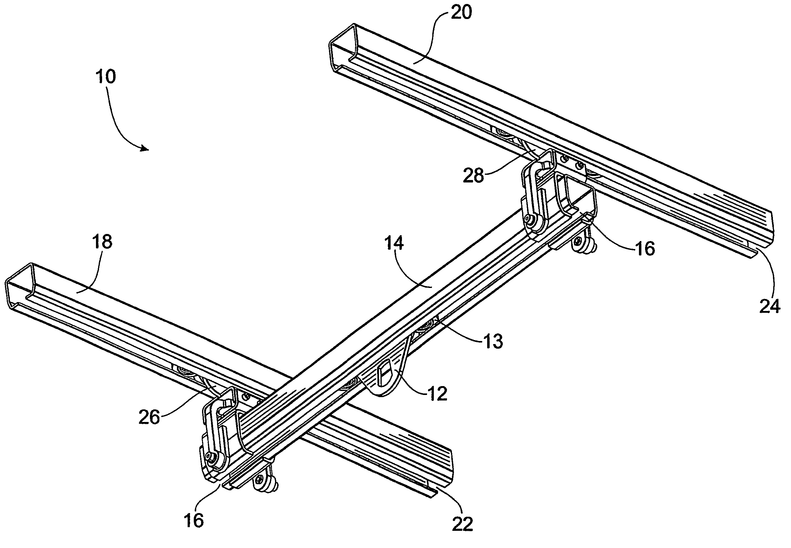
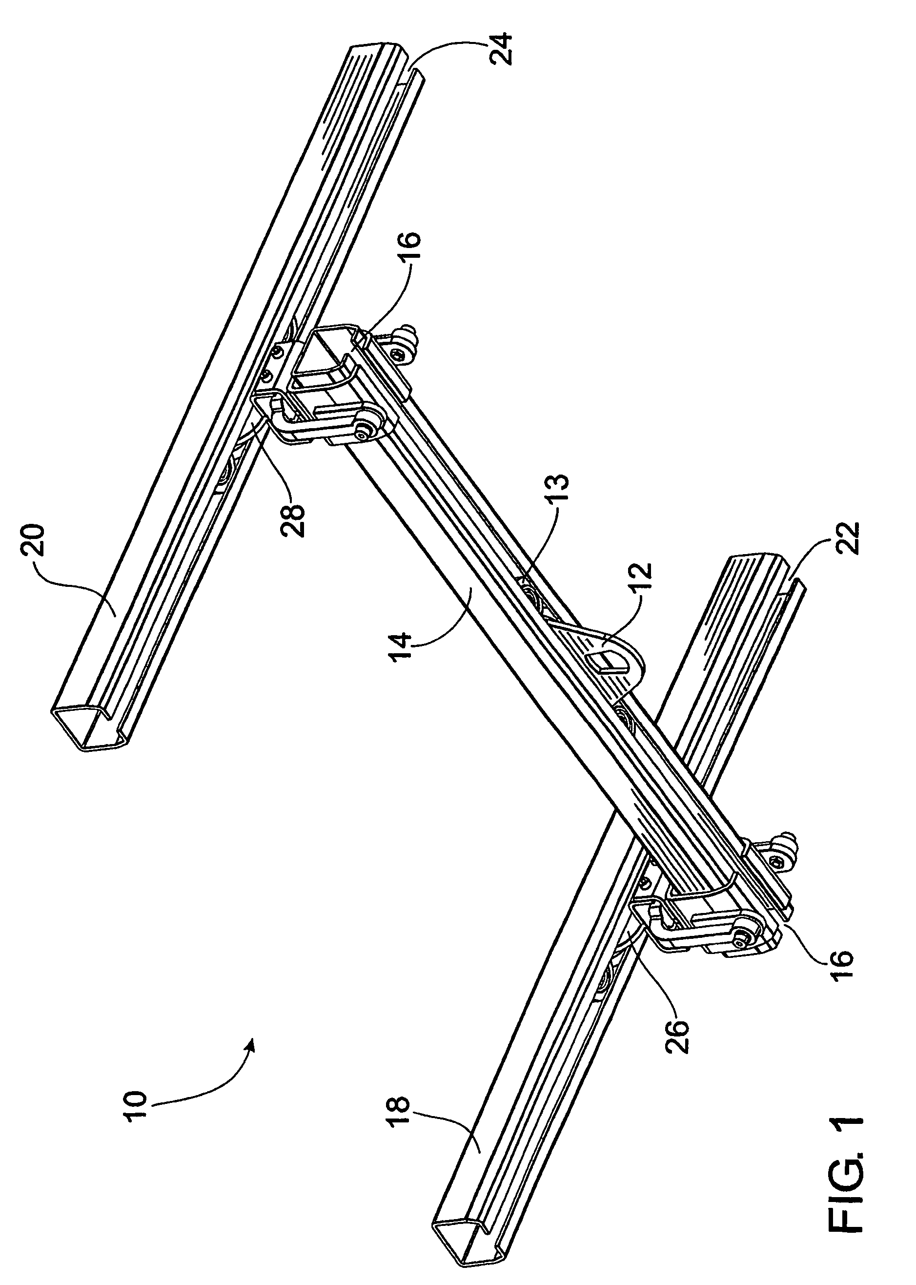
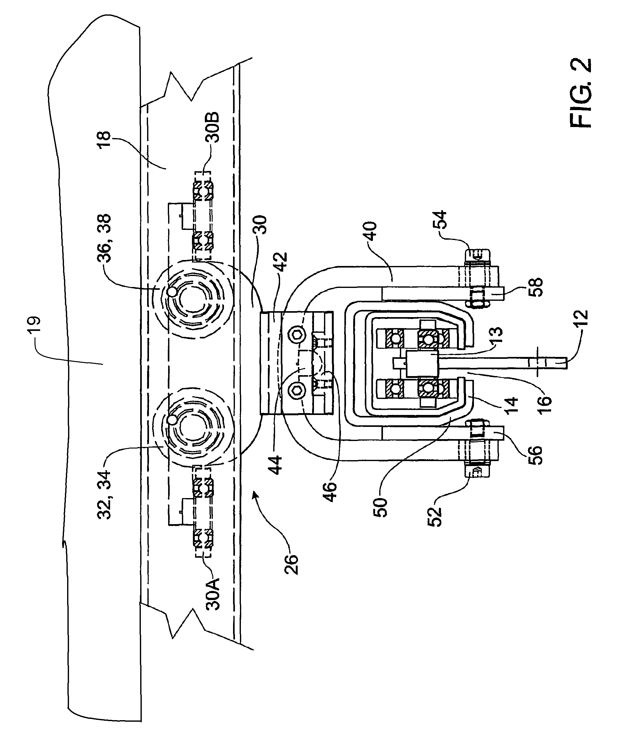
[0043]FIG. 1 illustrates a lifting assembly 10. A lifting device in the form of a manually operated crane (not illustrated) may be suspended from the lifting assembly by attachment means 12. The attachment means 12 could be a hook, chain or other suitable device. It is to be appreciated, that the lifting device could adopt any suitable form. For example, the lifting device could be a manually or an electrically operated crane.

[0044]The attachment means 12 is connected to a trolley 13. The trolley 13 is movably suspended from a bridge 14. The bridge 14 could be in the form of an open channel section, an I-beam, or any other suitable form. The trolley 13 includes trolley rollers being wheels, ball bearings or other suitable propulsion means. The rollers are capable of rolling longitudinally along the bridge 14. The trolley rollers could adopt any suitable form. In this respect, the trolley rollers could include plastic coated rolling surfaces for silent running. Alternatively, the rol...


PUM


Abstract

A lifting assembly comprising parallel guides (18, 20), a carriage (26, 28) associated with each parallel guide (18, 20) and movable along the length of the parallel guides, a displacement arm (40) pivotally connected to each carriage (26, 28) and pivotally supporting a bridge (14), preferably a trolley (13) located on the bridge (14) including attachment means (12) for supporting a lifting device.

Description

[0001]This is a continuation in part of PCT / AU03 / 00668 filed May 30, 2003 and published in English.FIELD OF THE INVENTION[0002]The present invention relates generally to an improved crane assembly. The invention has particular application to a manually operated suspended (or overhead) crane assembly, which is configured to provide easier operation for the assembly operator. The invention will therefore be described in this context. However, it will be appreciated that the invention has broader application and is not limited to that particular use.BACKGROUND OF THE INVENTION[0003]Manually operated suspended crane assemblies such as a gantry crane or bridge crane are used in a great variety of industrial and other applications for lifting and moving objects. Suspended crane assemblies can be designed to lift and move any practical weight.[0004]Existing suspended crane assemblies generally include a crane, which is suspended from a trolley that is, in turn, suspended from at least one ...

Claims


Application Information

Patent Timeline
Patent Type & Authority Patents(United States)
IPC IPC(8): B66C19/00B66C1/00B66C6/00B66C5/02B66C5/06B66C9/10B66C9/16B66C11/06B66C17/00F16C11/06F16D3/16
CPCB66C9/10B66C9/16B66C11/06B66C17/00B66C7/04
Inventor MCKAY, DOUGLAS MCGREGOR
Owner THE MCKAY
Why Eureka
Try Eureka