Turbomachine rotor blade

a technology of rotor blades and rotor blades, which is applied in the direction of liquid fuel engines, vessel construction, marine propulsion, etc., can solve the problems of increasing the weight of the flange and hence the rotor disk, and achieves the effect of simple, effective and economic

Active Publication Date: 2010-12-14
SN DETUDE & DE CONSTR DE MOTEURS DAVIATION S N E C M A
View PDF6 Cites 1 Cited by
  • Summary
  • Abstract
  • Description
  • Claims
  • Application Information

AI Technical Summary

Benefits of technology

[0006]The object of the present invention is in particular to provide a simple, effective and economic solution to these problems.
[0009]The invention therefore makes it possible to reduce the weight of the rotor blades without, for all that, modifying the scalloped rim of the flange because the circumferential distance between the lateral ends of the stops remains unchanged.

Problems solved by technology

However, this solution is not satisfactory because it makes it necessary in consequence to modify the scalloped rim of the flange, by increasing the circumferential extent of the solid portions of its rim, in order to retain the aforementioned slight circumferential clearance between the stops and the solid portions of the rim of the flange, which also leads to an increase in the weight of the flange and hence of the rotor disk.

Method used


Image

  • Turbomachine rotor blade
  • Turbomachine rotor blade
  • Turbomachine rotor blade

Examples


Embodiment Construction

[0021]Reference is made first to FIGS. 1 to 4 which illustrate the technique involved in the present invention.

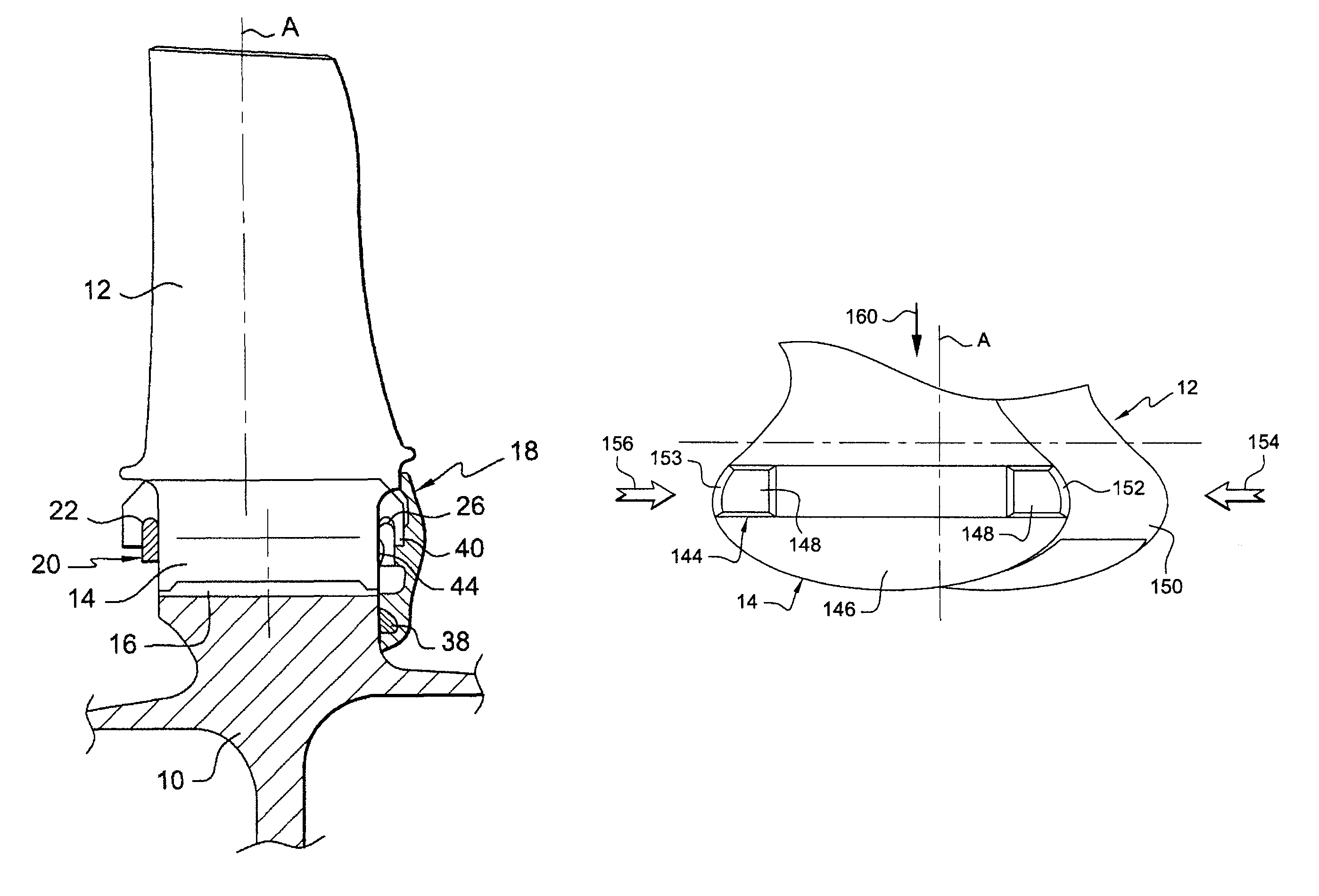
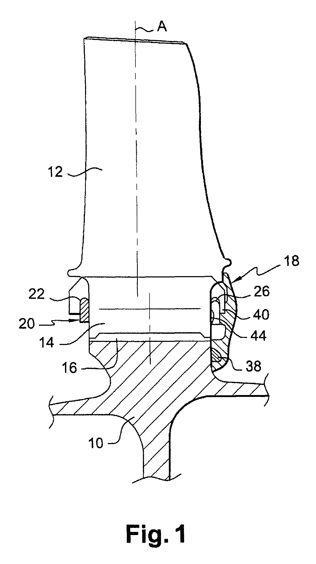
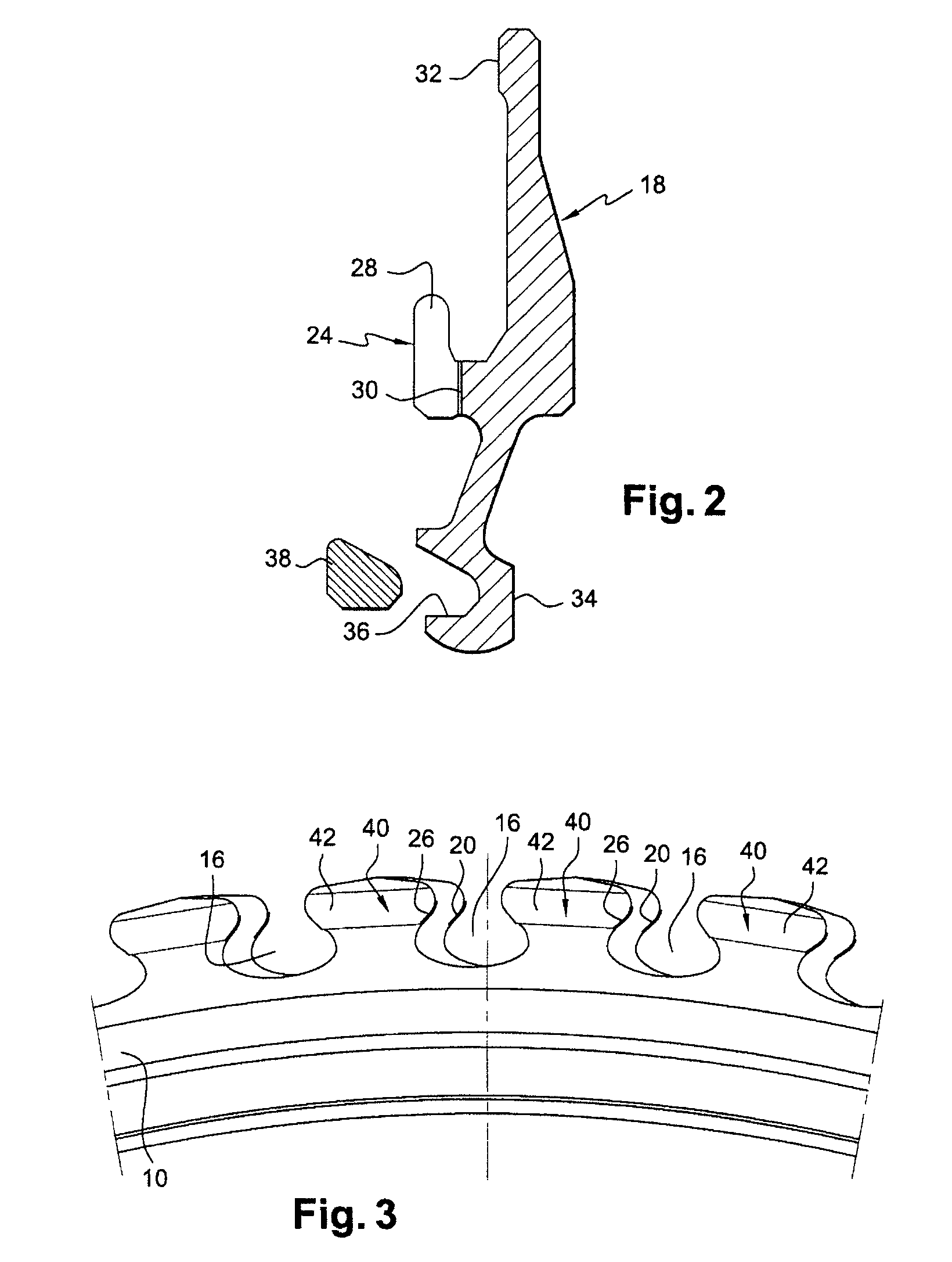
[0022]The rotor of a turbomachine compressor comprises a plurality of rotor disks, one of which is shown partially in FIGS. 1 and 3, each disk 10 supporting a plurality of substantially radial blades 12 whose roots 14 are engaged in axial channels 16 of the periphery of the disk 10.

[0023]The roots 14 of the blades are retained radially in the channels 16 of the disk by interaction of shapes, these channels 16 being for example dovetailed as shown in FIG. 3. The blades 12 are immobilized axially in the channels 16 by an annular flange 18 mounted on the downstream face of the disk 10 and by a locking ring 20 mounted on the upstream face of the disk.

[0024]The locking ring 20 is split and is radially compressed in order to be inserted into an annular groove 22 opening radially toward the inside of the upstream face of the disk 10. This ring 20 presses axially on the upstream en...


PUM


Abstract

A turbomachine rotor blade comprising a root (14) mounted in a channel of the periphery of a disk and held by an annular flange (18) which presses on the root (14) of the blade (12), this root comprising a stop (44) engaging in a matching cavity of the flange in order to stop it rotating about the axis of the disk, the central portion of the stop having a thickness less than that of the ends of the stop.

Description

[0001]The present invention relates to a rotor blade, in particular for a compressor of a turbomachine such as an aircraft turbojet or turboprop.BACKGROUND OF THE INVENTION[0002]The blades of a compressor stage comprise roots engaged in axial channels of the periphery of a rotor disk and held by an annular flange formed of several sectors that is mounted via an external annular rim in an internal annular groove of the downstream face of the disk. This flange presses axially at its radially external end on the downstream ends of the blade roots, and at its radially internal end on the downstream face of the disk by means of an annular sealing snap-ring.[0003]The internal annular rim of the groove of the disk and the annular rim of the flange are scalloped or crenellated in a matching manner, which makes it possible to bring the flange inside the annular groove of the disk by axial translation when the solid portions of the scalloped rim of the flange are in line with the hollow porti...

Claims


Application Information

Patent Timeline
Patent Type & Authority Patents(United States)
IPC IPC(8): F01D5/30
CPCF01D5/3015Y02T50/671Y02T50/60
Inventor CLOAREC, YVON
Owner SN DETUDE & DE CONSTR DE MOTEURS DAVIATION S N E C M A
Why Eureka
Try Eureka