Hub for a propeller having variable pitch blades

a technology of variable pitch blades and hubs, which is applied in the direction of liquid fuel engine components, wind motors with parallel air flow, wind motors with perpendicular air flow, etc., can solve the problems of extensive structural damage around the turbomachine, and achieve the effect of simple, effective and economic

Active Publication Date: 2015-03-03
SN DETUDE & DE CONSTR DE MOTEURS DAVIATION S N E C M A
View PDF7 Cites 0 Cited by
  • Summary
  • Abstract
  • Description
  • Claims
  • Application Information

AI Technical Summary

Benefits of technology

[0008]A notable aim of the invention is to provide a s

Problems solved by technology

In the event of fracture of the polygonal ring, the blades could esca

Method used


Image

  • Hub for a propeller having variable pitch blades
  • Hub for a propeller having variable pitch blades
  • Hub for a propeller having variable pitch blades

Examples


Embodiment Construction

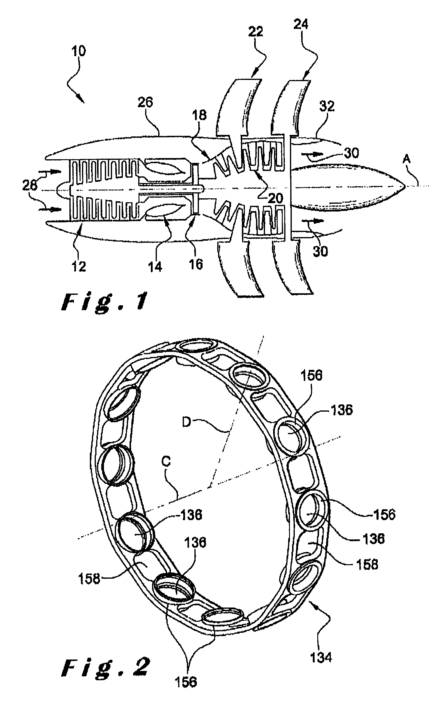
[0020]Refer first to FIG. 1, which shows an unducted fan (or open rotor) turbomachine 10 that includes, in the upstream to downstream direction, in the direction of flow of the gases inside the turbomachine, a compressor 12, an annular combustion chamber 14, a high-pressure turbine 16, and two low-pressure turbines 18, 20 that contrarotate, i.e. that turn in opposite directions about the longitudinal axis A of the turbomachine.

[0021]Each of these downstream turbines 18, 20 is constrained to rotate with an external propeller 22, 24 extending radially outside the nacelle 26 of the turbomachine. This nacelle 26 is substantially cylindrical and extends along the axis A around the compressor 12, the combustion chamber 14, and the turbines 16, 18 and 20.

[0022]The airflow 28 that enters the turbomachine is compressed and then mixed with fuel and burned in the combustion chamber 14, the combustion gases then passing through the turbines to drive rotation of the propellers 22, 24 that supply...


PUM


Abstract

A hub for a propeller having variable pitch blades for a turbine engine, for example for a propfan turbine engine. The propeller hub includes: a polygonal ring having substantially radial cylindrical housings distributed about a central axis of the ring for receiving the blades; a rotor element for the turbine of the turbine engine; a supporting flange attached to the ring so as to connect the ring to the rotor element; and a plurality of backup retaining members linked to the rotor element, and each of which includes at least one bearing surface opposite an outer surface of the ring with a radial spacing.

Description

BACKGROUND OF THE INVENTION[0001]1. Field of the Invention[0002]The present invention concerns a hub for a propeller with variable pitch blades for a turbomachine of the unducted fan or open rotor type.[0003]2. Description of the Related Art[0004]The fan of a turbomachine of this type typically comprises coaxial external upstream and downstream contrarotating propellers each driven in rotation by a turbine of the turbomachine and extending substantially radially outside the nacelle of the turbomachine.[0005]Each propeller comprises a hub including a rotor element of the turbine and a polygonal ring fixed to said rotor element and having substantially radial cylindrical housings distributed around the longitudinal axis of the turbomachine and receiving the blades of the propeller.[0006]The blades may turn in the housings of the polygonal ring and are driven in rotation about the axes of the blades by appropriate means to adjust the angular pitch of the blades to optimize it as a func...

Claims


Application Information

Patent Timeline
IPC IPC(8): F04D29/32B64C11/02F01D5/02F01D21/04B64C11/48B64D27/02F01D1/26F01D5/30F01D7/00F01D7/02F02C6/20F02C9/58
CPCF04D29/321B64C11/02B64C11/48F01D1/26F01D5/025F01D5/3007F01D7/00F01D7/02F02C6/206F02C9/58Y02T50/671B64D2027/026Y02T50/66F05D2220/325F05D2260/74F05D2260/79Y02T50/60
Inventor BOSTON, ERIC JACQUESBOURU, MICHEL ANDREJABLONSKI, LAURENTJOLY, PHILIPPE GERARD EDMOND
Owner SN DETUDE & DE CONSTR DE MOTEURS DAVIATION S N E C M A
Why Eureka
Try Eureka