Turbine engine with a contra-rotating turbine for an aircraft

a technology of contra-rotating turbine and turbine engine, which is applied in the direction of machines/engines, non-positive displacement engines, mechanical devices, etc., can solve the problems of high complexity of design, complex architecture, and current integration solutions that are particularly complex, and achieves simple, effective and economic solutions.

Active Publication Date: 2022-06-07
SN DETUDE & DE CONSTR DE MOTEURS DAVIATION S N E C M A
View PDF14 Cites 0 Cited by
  • Summary
  • Abstract
  • Description
  • Claims
  • Application Information

AI Technical Summary

Benefits of technology

[0012]The present invention proposes an improvement to the technology described above, which represents a simple, effective and economic solution to at least some of the problems mentioned above.
[0018]This solution is advantageous for several reasons. First, from a simplification and mounting standpoint, since the number of bearings is limited and can be of two only, namely one for guiding the second shaft with respect to the first shaft and another for guiding the second shaft with respect to the stator casing. Moreover, from a volume and integration point of view, they are also simplified due to the number and the position of the bearings. These bearings are actually situated in one same zone situated downstream from the contra-rotating turbine and upstream from the reduction gear. They are thus positioned to facilitate the transmission of forces from the first shaft to the stator casing, by avoiding urging the reduction gear. In addition, the reduction gear is mainly connected to three members, only one of which is called “rigid”, the two others being called “flexible”. Indeed, in the configuration above, due to the position of the bearings and the limitation of their number, the first shaft forms a flexible member connecting to the reduction gear, as is the case of the second shaft. Only the planet carrier, which is connected to the stator casing, can be considered as a rigid member.

Problems solved by technology

However, increasing the rotation speed of the turbine involves increasing the centrifugal forces that it undergoes, and therefore highly complicates its design.
This architecture is complex because of its mechanical integration: the mechanical reduction gear is situated downstream from the turbine engine, radially inside a stator casing called exhaust casing.
Current integration solutions are particularly complex, as there are numerous inter-shaft bearings which are particularly difficult to lubricate.
Turbine radial loads are likely to pass into the reduction gear, which is extremely damaging for the reduction gear to perform correctly.
Finally, the volume is not optimised, in particular with the presence of bearings under the planet gear or sun gear of the reduction gear, which limits the radial integration of the reduction gear.

Method used


Image

  • Turbine engine with a contra-rotating turbine for an aircraft
  • Turbine engine with a contra-rotating turbine for an aircraft
  • Turbine engine with a contra-rotating turbine for an aircraft

Examples


Embodiment Construction

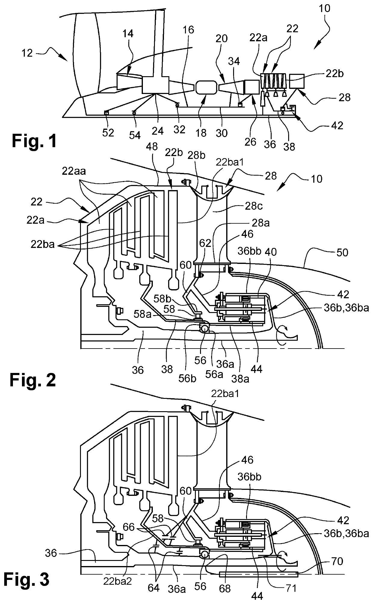
[0039]FIG. 1 very schematically represents a turbine engine 10 with a contra-rotating turbine for an aircraft.

[0040]This turbine engine 10 comprises, from upstream to downstream, in the direction of flow of the gases, a fan 12, a low-pressure compressor 14, a high-pressure compressor 16, an annular combustion chamber 18, a high-pressure turbine 20 and a contra-rotating turbine 22. A person skilled in the art will appreciate that the term “turbine engine” designates just as well, a turbojet, a turboprop or a turboshaft for which the specific configuration of the different elements can be different.

[0041]The reference 24 designates an intermediate casing situated between the compressors 14 and 16, and the reference 26 designates a turbine casing (of the TVF type) situated between the turbines 20 and 22. Finally, the reference 28 designates an exhaust casing (of the TRF type). These casings form the structure of the turbine engine: they support the bearings which guide the shafts in ro...


PUM


Abstract

Turbine engine (10) with a contra-rotating turbine for an aircraft,the turbine engine comprising a contra-rotating turbine (22) whose first rotor (22a) is configured to rotate in a first direction of rotation and is connected to a first turbine shaft (36), and a second rotor (22b) is configured to rotate in an opposite direction of rotation and is connected to a second turbine shaft (38), the first rotor comprising turbine wheels (36a) inserted between turbine wheels (38a) of the second rotor,the turbine engine further comprising a mechanical reduction gear (42) with an epicyclic gear train which comprises a sun gear (44) driven in rotation by said second shaft, a ring gear (40) driven in rotation by said first shaft, and a planet carrier (46) fixed to a stator casing (28) of the turbine engine situated downstream from the contra-rotating turbine with respect to direction of flow of the gases in the turbine engine,the turbine engine further comprising a bearing (56) for guiding the second shaft with respect to the first shaft, and a bearing for guiding the second shaft with respect to said stator casing,characterised in that said bearings are all situated downstream from the trailing edge of the last turbine wheel of the contra-rotating turbine and upstream from the reduction gear.

Description

TECHNICAL FIELD[0001]The present invention concerns a turbine engine with a contra-rotating turbine for an aircraft.STATE OF THE ART[0002]The state of the art comprises documents EP-A2-2 199 568, WO-A1-2015 / 189524 and EP-A1-1 577 491.[0003]Conventionally, an aircraft turbine engine comprises, from upstream to downstream, in the direction of flow of the gases, a fan, a low-pressure compressor, a high-pressure compressor, an annular combustion chamber, a high-pressure turbine and a low-pressure turbine. The rotor of the low-pressure compressor is driven by the rotor of the low-pressure turbine, and the rotor of the high-pressure compressor is driven by the rotor of the high-pressure turbine.[0004]From an engine performance and consumption point of view, it is advantageous to maximise the rotation speed of the low-pressure turbine, as this makes it possible to obtain a better efficiency of the turbine. However, increasing the rotation speed of the turbine involves increasing the centri...

Claims


Application Information

Patent Timeline
Patent Type & Authority Patents(United States)
IPC IPC(8): F01D1/24F02K3/072F02C3/067F02C7/06F02C7/36
CPCF02K3/072F01D1/24F02C3/067F02C7/06F02C7/36F05D2250/75F05D2260/40311F02C3/107F02K3/06
Inventor LEVISSE, PAUL GHISLAIN ALBERTBELMONTE, OLIVIERBENSLAMA, YANIS
Owner SN DETUDE & DE CONSTR DE MOTEURS DAVIATION S N E C M A
Why Eureka
Try Eureka