Turbomachine exhaust case drain

a turbomachine and exhaust case technology, applied in the direction of machines/engines, stators, liquid fuel engines, etc., can solve the problems of inability to easily control, long and difficult operation, and inability to stabilize liquids, so as to simplify the mounting operation, reduce work time, and improve efficiency

Active Publication Date: 2012-10-02
SN DETUDE & DE CONSTR DE MOTEURS DAVIATION S N E C M A
View PDF8 Cites 0 Cited by
  • Summary
  • Abstract
  • Description
  • Claims
  • Application Information

AI Technical Summary

Benefits of technology

[0006]The object of the present invention is to provide a simple, effective and economic solution to this problem, particularly by simplifying the operation of mounting the drain on the exhaust case and by considerably reducing the work time required for this mounting operation.
[0009]Fastening the drain by crimping avoids having to employ an annular weld, the drawbacks of which have been specified above, and thus offers a significant time saving when mounting the drain on the exhaust case of the turbomachine, the total mounting time being approximately 30 minutes instead of several hours.
[0011]The expansion of the drain, under the effect of the rise in temperature during operation, causes a jamming effect whereby the drain is jammed in the orifice in the case, thus making it possible to improve the fastening of the drain to the case.
[0013]This configuration makes it possible to obtain optimum crimping and to minimize the risks of losing the drain during operation or during a maintenance phase on the turbomachine.
[0017]It is possible to ensure good sealing between the drain and the exhaust case on which it is mounted, while at the same time maintaining the planarity of the internal wall of the groove of this case about its discharge orifice.

Problems solved by technology

Stagnation of these liquids is not desirable, particularly given the risks of fire and those associated with freezing, and for this reason the exhaust cases generally comprise an orifice provided with a drain in this dead region to discharge the liquids toward the outside of the turbomachine.
However, carrying out this welding is a long and difficult operation which cannot be readily controlled and which is relatively dangerous for the operator, this operation particularly requiring manual touch-ups to remove the excess material which projects into the drain and into the primary flow path in the region of the internal wall of the case.

Method used


Image

  • Turbomachine exhaust case drain
  • Turbomachine exhaust case drain
  • Turbomachine exhaust case drain

Examples


Embodiment Construction

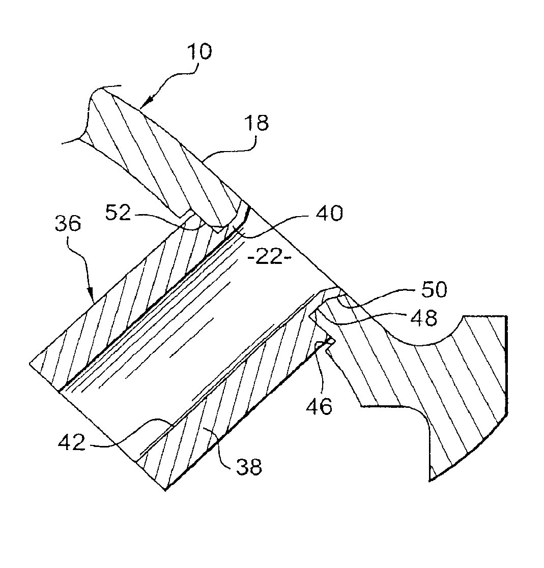
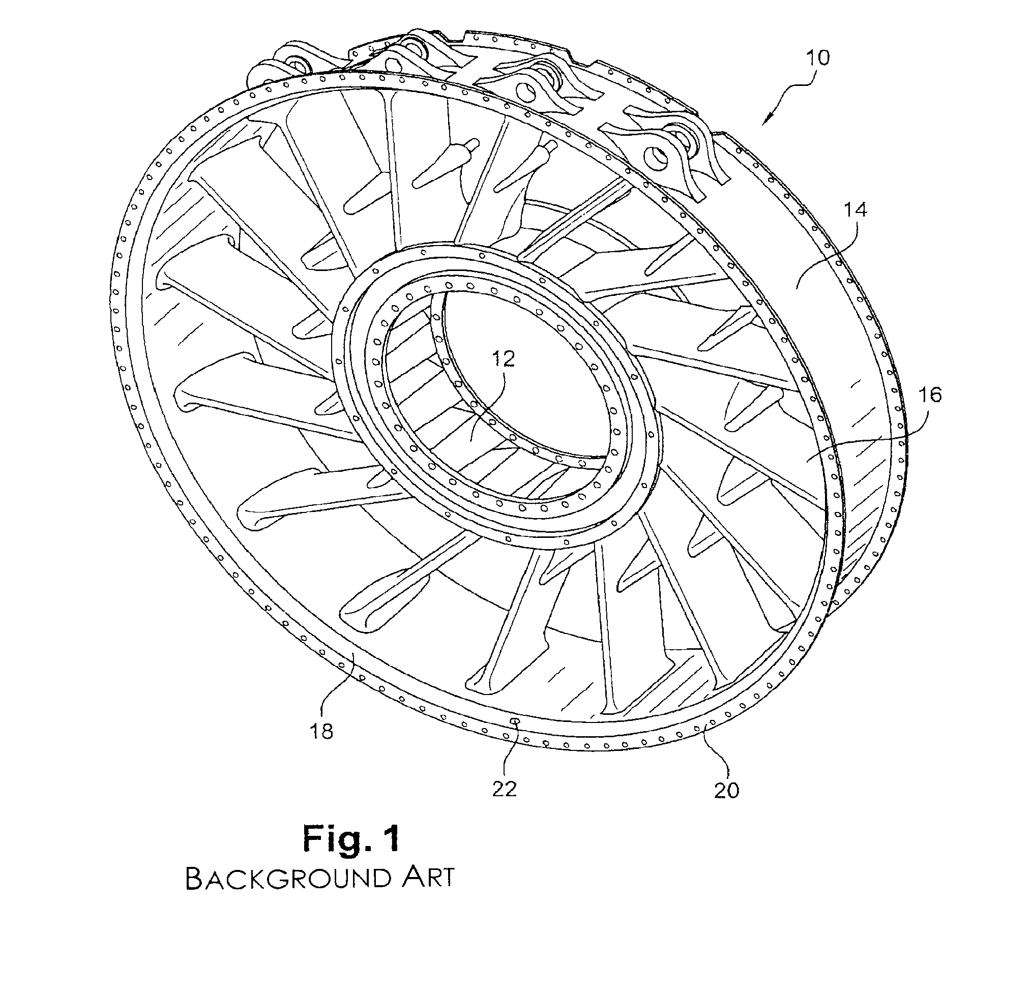
[0025]Reference will be made first of all to FIG. 1, which shows a turbomachine exhaust case 10 of a known type, as seen from the upstream end, comprising two coaxial cylindrical shells, one inner shell 12 and one outer shell 14, connected by oblique arms 16. The outer shell 14 includes at its upstream end an annular groove 18 which is situated downstream and in the vicinity of the upstream mounting flange 20 of the exhaust case, a region of which groove situated “at 6 o'clock”, that is to say at the bottom, is perforated with a discharge orifice 22 provided with a drain intended to outwardly discharge liquids liable to be collected in this groove.

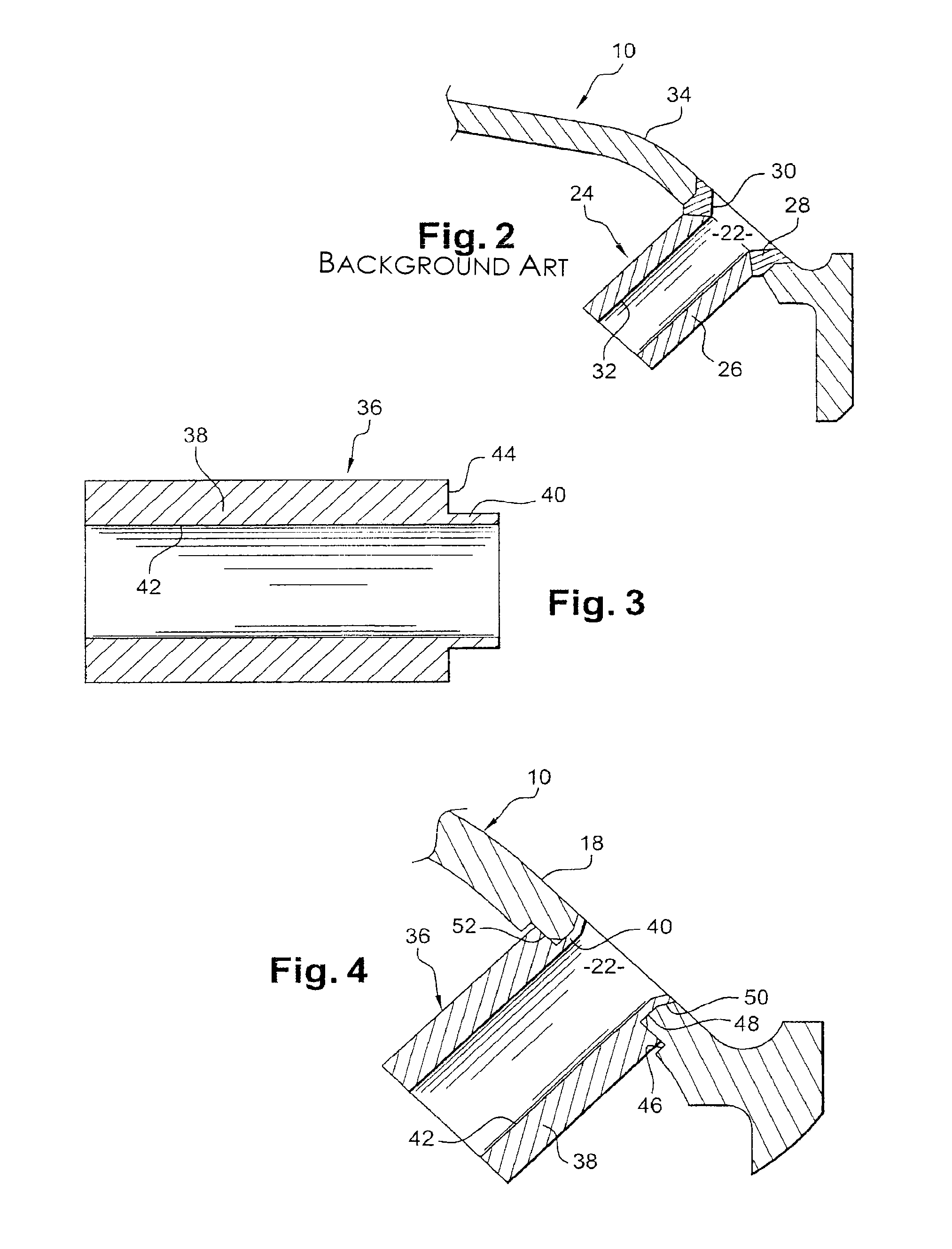
[0026]FIG. 2 is a larger-scale view of the discharge orifice 22 and its drain 24, which is formed by a tubular cylindrical body 26 fastened to the rim of the orifice 22 by an annular weld 28 formed around the periphery of this orifice. The surface 30 of the weld 28 that connects the internal wall 32 of the drain to the internal wall 34 of ...


PUM


Abstract

A turbomachine exhaust case having an annular groove perforated with an orifice in which there is mounted a drain, which is formed by a tubular cylindrical body, for discharging liquids retained in this groove is disclosed. The drain includes a skirt, formed at one end of the cylindrical body, for fastening the drain by crimping in the orifice in the groove of the case.

Description

[0001]The present invention relates to a liquid discharge drain in an exhaust case of a turbomachine such as a jet engine.BACKGROUND OF THE INVENTION AND DESCRIPTION OF THE PRIOR ART[0002]The exhaust case of a turbomachine generally comprises a groove which is formed downstream and in the vicinity of the upstream mounting flange of this case and which constitutes a dead region, that is to say one shielded from the primary air flow. It frequently occurs that liquids, such as water, fuel and oil, are retained in a region situated “at 6 o'clock”, that is to say toward the bottom, in this groove.[0003]Stagnation of these liquids is not desirable, particularly given the risks of fire and those associated with freezing, and for this reason the exhaust cases generally comprise an orifice provided with a drain in this dead region to discharge the liquids toward the outside of the turbomachine.[0004]This drain is conventionally formed by a cylindrical body which is welded to the case at the ...

Claims


Application Information

Patent Timeline
Patent Type & Authority Patents(United States)
IPC IPC(8): F01D11/00F01D25/32F01B31/18F04D29/00
CPCF01D25/30F01D25/32F05D2260/602F05D2250/231
Inventor POMMIER, NICOLASSCHNELL, CHRISTIAN RENE
Owner SN DETUDE & DE CONSTR DE MOTEURS DAVIATION S N E C M A
Why Eureka
Try Eureka