Variable-pitch vane of a turbomachine

a variable-pitch vane, turbomachine technology, applied in the direction of machines/engines, stators, liquid fuel engines, etc., can solve the problems of difficult prediction of relative movements in the axial direction between the rotor and the stator, low degree of efficiency of the labyrinth seal formed by the seal teeth of the rotor, and the block of abradable material being worn. , to achieve the effect of simple, effective and economi

Active Publication Date: 2012-06-26
SN DETUDE & DE CONSTR DE MOTEURS DAVIATION S N E C M A
View PDF22 Cites 5 Cited by
  • Summary
  • Abstract
  • Description
  • Claims
  • Application Information

AI Technical Summary

Benefits of technology

[0008]A particular object of the invention is to provide a simple, effective and economic solution to these problems.
[0013]the axial movement of the internal ring makes it possible during operation to vary the relative position of the blocks of abradable material and the seal teeth. It is thus possible, while in cruise mode for example, to move the blocks of abradable material axially in the upstream direction or in the downstream direction such that the seal teeth are not situated opposite channels in the block but, on the contrary, are situated facing surfaces of this block that are not worn or are less worn. The radial clearances between the seal teeth and the blocks of abradable material can therefore be best optimized and adjusted on the basis of the various operating modes of the turbomachine;
[0014]the axial movement of the internal ring can also be controlled to follow the axial movements of the rotor of the turbomachine during the various operating modes. This makes it possible to optimize the axial clearances between the internal ring and the rotor and to reduce the axial dimension and the mass of the turbomachine. The better control over the clearances also makes it possible to reduce the number of seal teeth of the rotor, for example from three to two per stage, these seal teeth being expensive.
[0017]The rotational movement of the vane causes a movement of the internal ring that can have an axial component and a tangential component. It may prove necessary in certain cases to mount the internal pivot of the vane in the housing of the internal ring by a swiveling or tilting connection in order to allow the axial movement of the ring and avoid the occurrence of stresses at the internal pivot of the vane.

Problems solved by technology

The operating cycle of the turbomachine comprises transient modes leading to relative movement in the axial and radial directions between the rotor and the stator, which results in considerable wear on the blocks of abradable material caused by the seal teeth of the rotor rubbing against these blocks.
During cruise mode, the seal teeth are situated radially set back from these blocks and facing previously formed channels, this resulting in considerable radial clearances between the tips of the seal teeth and the blocks of abradable material, and hence in a low degree of efficiency of the labyrinth seal formed by the seal teeth of the rotor.
Moreover, the relative movements in the axial direction between the rotor and the stator are difficult to predict.
However, this solution is not satisfactory since it entails increasing the axial dimension of the engine and the mass of the turbomachine.

Method used


Image

  • Variable-pitch vane of a turbomachine
  • Variable-pitch vane of a turbomachine
  • Variable-pitch vane of a turbomachine

Examples


Embodiment Construction

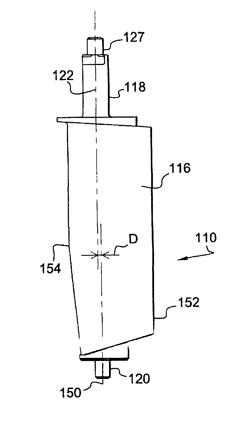
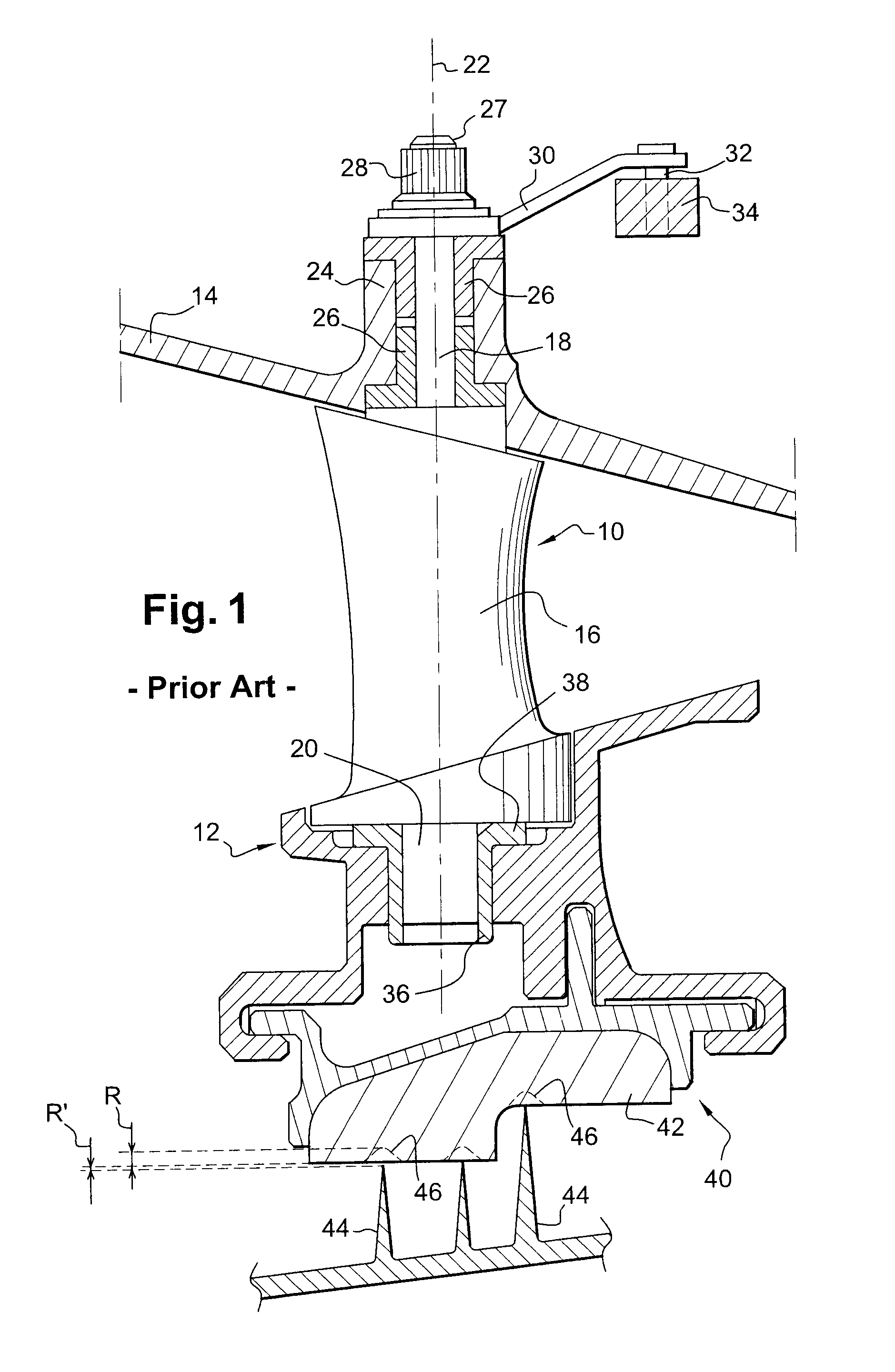
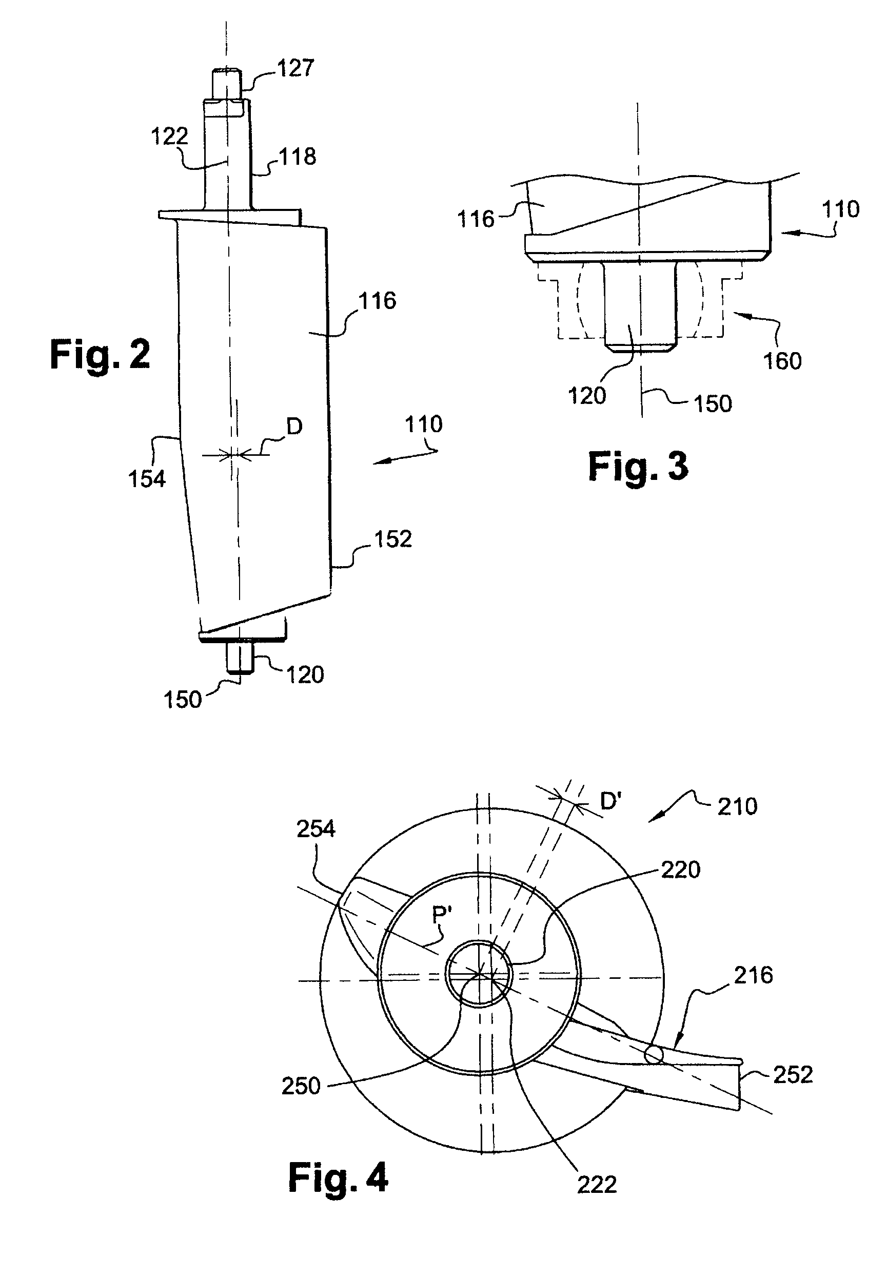
[0026]FIG. 1 shows a stator stage of variable-pitch vanes 10 of a high-pressure compressor of a turbomachine, these vanes 10 being distributed about the axis of the turbomachine and extending between an internal ring 12 and an external ring 14 of the turbomachine.

[0027]Each vane 10 comprises an airfoil 16 connected at each of its radially internal and external ends to a radial cylindrical pivot 18, 20 which extends along the axis 22 of rotation of the vane.

[0028]The external cylindrical pivot 18, or actuating pivot, is fitted into the housing of a cylindrical duct 24 of the casing and is centered and rotationally guided in this duct by cylindrical bushes 26 mounted around the external pivot 18.

[0029]The radially external end 27 of the external pivot 18 is fastened by means of a nut 28 to one end of an actuating lever 30. The other end of the actuating lever 30 bears a finger 32 which is rotationally guided in an actuating ring 34 which extends around the axis of the turbomachine, ou...


PUM


Abstract

A stator stage of a compressor of a turbomachine including an annular row of variable-pitch vanes is disclosed. Each vane includes an external cylindrical pivot defining the axis of rotation of the vane, and an internal cylindrical pivot mounted in a housing of an internal ring. The internal pivot of each vane extends along an axis substantially parallel to the axis of rotation of the vane and at a distance from this axis, and is mounted in the housing of the ring by a swiveling or a tilting system.

Description

[0001]The present invention relates to a variable-pitch vane and also to a stator stage of variable-pitch vanes for a turbomachine such as an aircraft turbojet or turboprop.BACKGROUND OF THE INVENTION AND DESCRIPTION OF THE PRIOR ART[0002]In a turbomachine, stages of variable-pitch stator vanes are mounted between rotor disks of a compressor. These variable-pitch vanes are supported by a casing of the stator and can be adjusted in position about their axes to optimize the flow of the gases in the engine of the turbomachine.[0003]In the current art, a variable-pitch vane comprises a substantially cylindrical axial pivot at each of its ends, these pivots defining the axis of rotation of the vane. The radially external pivot, termed actuating pivot, is fitted into the housing of a substantially radial or slightly inclined duct of a casing of the turbomachine and is connected by a lever to an actuating ring operated by a ram, an electric motor, or the like. The rotation of the actuating...

Claims


Application Information

Patent Timeline
Patent Type & Authority Patents(United States)
IPC IPC(8): F01D17/12
CPCF01D11/001F01D17/162F04D29/563Y02T50/671F05D2250/312F04D29/102F05D2260/56Y02T50/60
Inventor CLOAREC, YVON
Owner SN DETUDE & DE CONSTR DE MOTEURS DAVIATION S N E C M A
Why Eureka
Try Eureka