Coaxial cable connector enhancing tightness engagement with a coaxial cable

a technology of coaxial cable and connector, which is applied in the direction of connections, basic electric elements, electric devices, etc., can solve the problems of unsatisfactory tightness between the connector and the cable, and achieve the effect of enhancing tightness and easy operation

Active Publication Date: 2010-12-14
EZCONN
View PDF10 Cites 125 Cited by
  • Summary
  • Abstract
  • Description
  • Claims
  • Application Information

AI Technical Summary

Benefits of technology

[0006]An objective of the present invention is to provide a coaxial cable connector, which is composed of simplified components and is easy to operate for providing tight engagement with a coaxial cable.
[0007]To realize the above objective, the present invention provides a coaxial cable connector comprising a connection head and a sleeve assembly coupled to the connection head. The sleeve assembly comprises a tube, a sleeve, and a metal collar. The tube is received in the sleeve. An end of the sleeve forms in sequence a retention section, a buffering section, and an accommodation section. The retention section and the buffering section have a connection portion therebetween forming a contact section. The metal collar is fit in the retention section with an end of the metal collar positioned against the contact section. As such, the sleeve assembly receives a coaxial cable to insert therein from a rear end thereof in such a way that an insulator layer of a front end of the coaxial cable is set substantially flush with a front end of the tube and the sleeve assembly is then acted upon by a force applied by a tool to drive the metal collar frontward against the contact section for breaking and separating the retention section from the sleeve to further move frontward along a surface of the buffering section. Due to a constraint imposed by the metal collar, the buffering section is compressed downward to enhance tightness of engagement between the coaxial cable and the connector.

Problems solved by technology

Carelessness in using the tool may lead to undesired un-tight engagement between the connector and the cable.

Method used


Image

  • Coaxial cable connector enhancing tightness engagement with a coaxial cable
  • Coaxial cable connector enhancing tightness engagement with a coaxial cable
  • Coaxial cable connector enhancing tightness engagement with a coaxial cable

Examples


Embodiment Construction

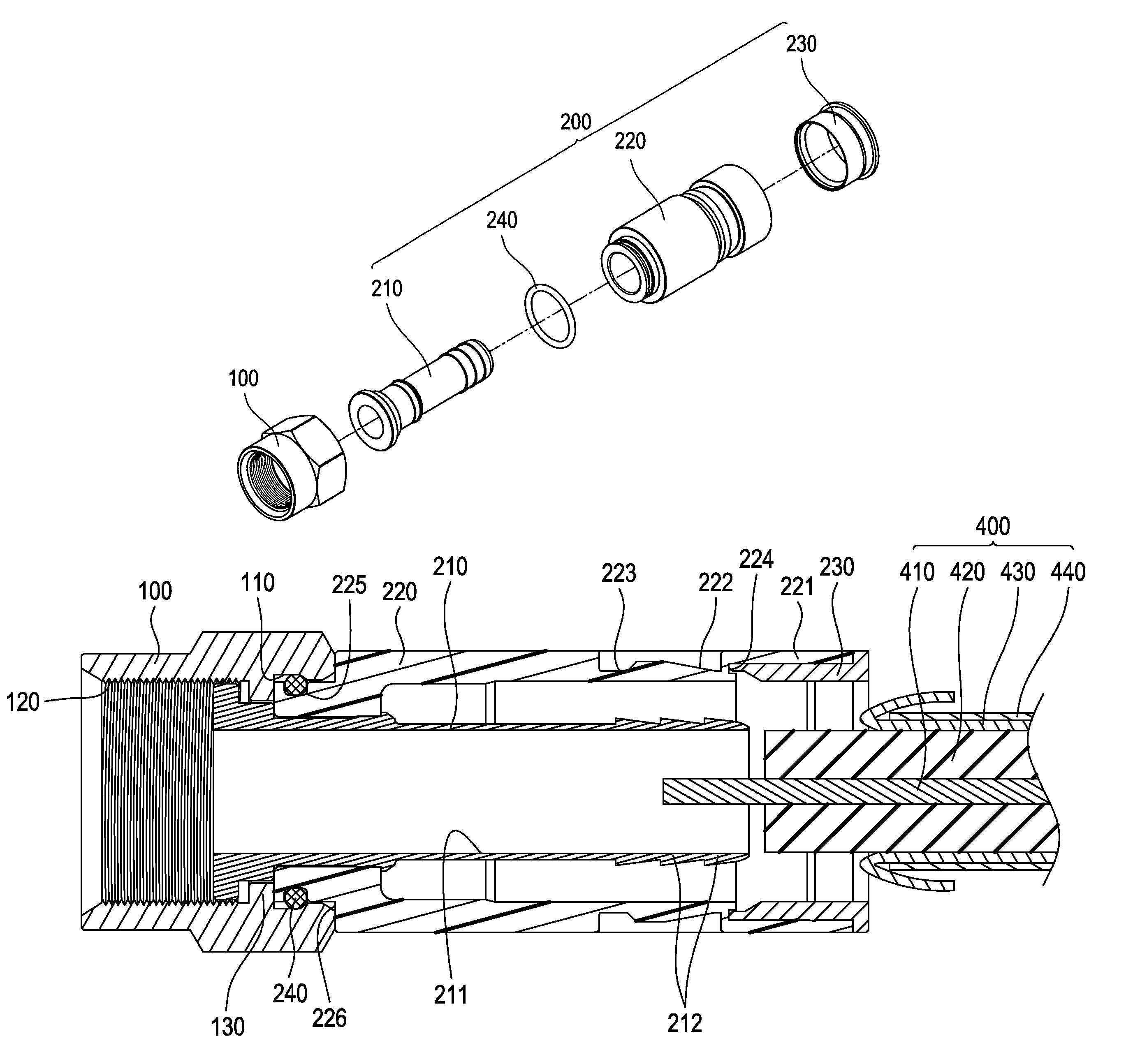
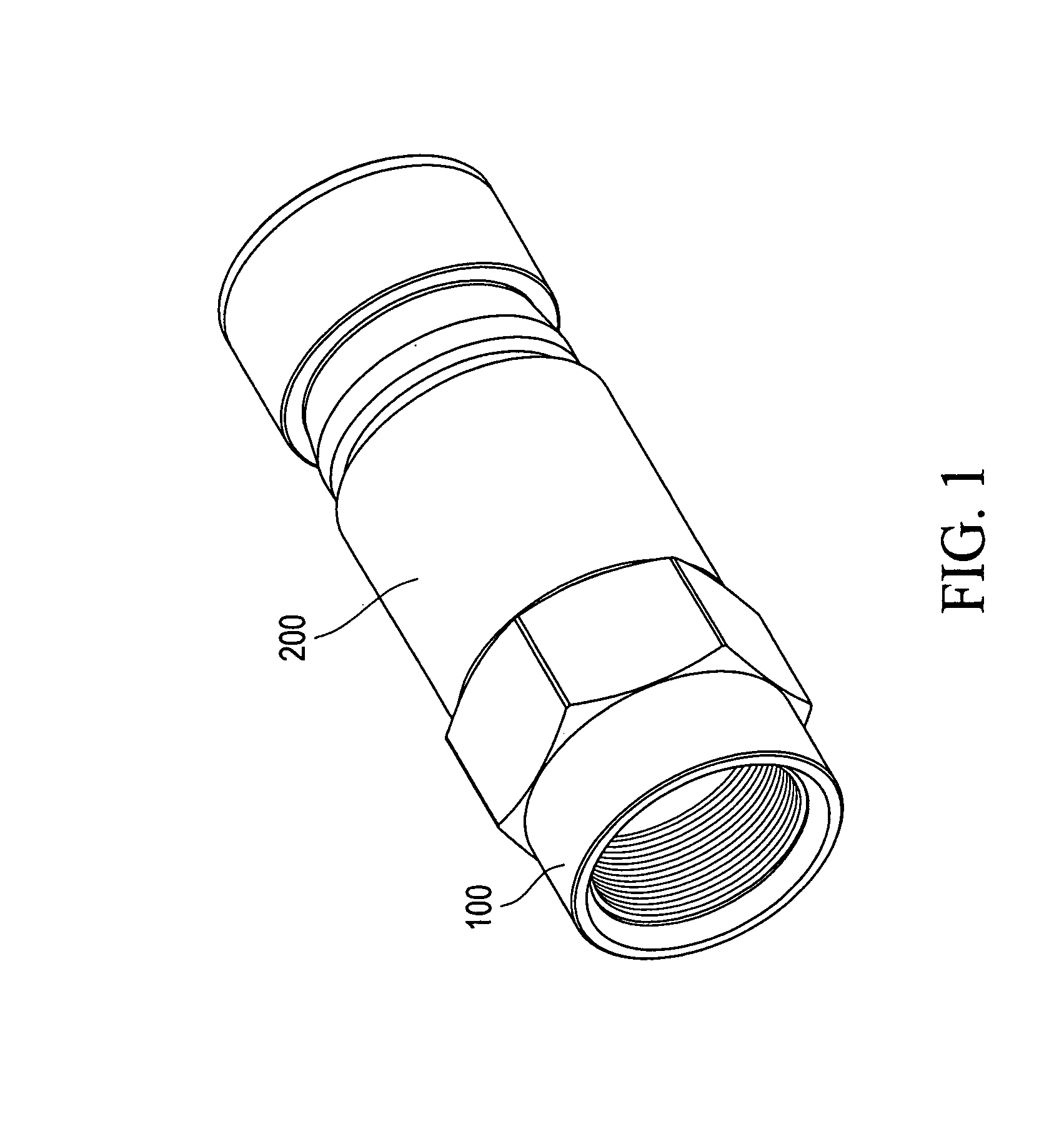
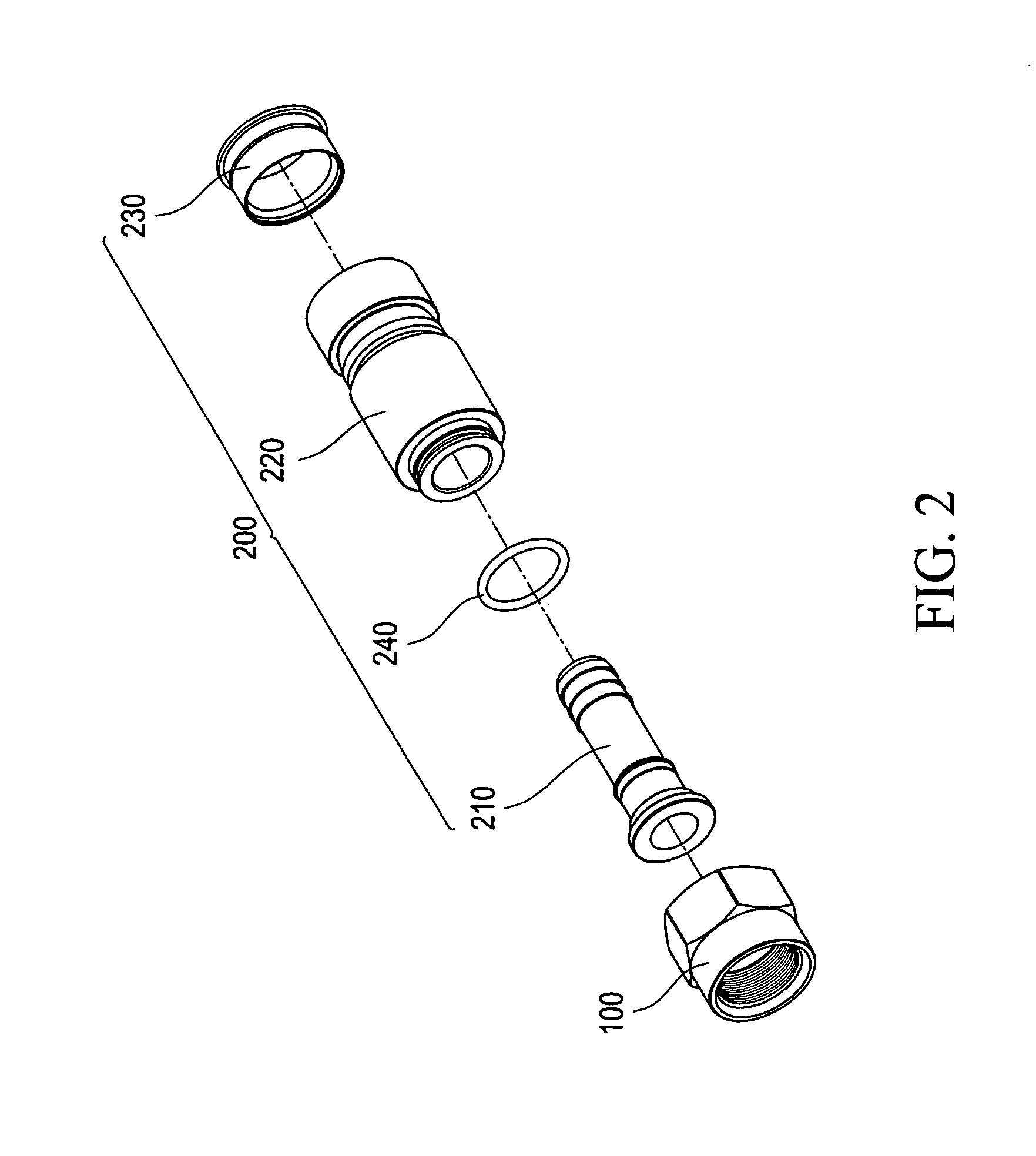
[0015]With reference to the drawings and in particular to FIGS. 1-3, a coaxial cable connector constructed in accordance with the present invention generally comprises: a connection head 100 and a sleeve assembly 200. In the embodiment illustrated, the connection head 100 is an F type connection head, which is given for explanation purpose. The connection head 100 has an outer circumference having an axial end portion forming a hexagonal shape. Inside the hexagonal shape, a first groove 110 is formed in an inside surface. Further, the inside surface of the connection head 100 also forms an inner thread 120 and an inner flange 130. It is apparent that the connection head 100 of the coaxial cable connector of the present invention can be alternatively embodied as a Bayonet Neill-Concelman (BNC) type connection head, an Radio Corporation of America (RCA) type connection head, or an International Electrotechnical Commission (IEC) type connection head (respectively shown in FIGS. 5A-5C)....


PUM


Abstract

A coaxial cable connector includes a connection head and a sleeve assembly coupled to the connection head. The sleeve assembly includes a tube, a sleeve, and a metal collar. The sleeve assembly receives a coaxial cable to insert therein from a rear end thereof in such a way that an insulator layer of a front end of the coaxial cable is set substantially flush with a front end of the tube and the sleeve assembly is then acted upon by a force applied by a tool to drive the metal collar frontward against the contact section of the sleeve for breaking and separating the retention section of the sleeve from the sleeve to further move frontward along a surface of the buffering section of the sleeve. Due to a constraint imposed by the metal collar, the buffering section is compressed downward to enhance tightness of engagement between the coaxial cable and the connector.

Description

FIELD OF THE INVENTION[0001]The present invention relates to a structure of coaxial cable connector that enhances tightness engagement with a coaxial cable, and is particularly fit for cables for transmission of signals, such as a coaxial cable or the likes.BACKGROUND OF THE INVENTION[0002]A conventional cabled television system or a shared antenna television system comprises a cable that is connected to a distributor from which branch cables extend for connection to end users in order to receive and transmit signals of the television system. The main cable comprises a coaxial cable having an end to which a coaxial cable connector is mounted for connection with the distributor.[0003]A conventional coaxial cable connector is shown in FIG. 6 of the attached drawings, which comprises an F type coaxial cable connector comprising a connector body A, which comprises a clamp barrel A1, a hollow plug B coaxially received in the clamp barrel A1, and an O-ring C and a nut D set around the plu...

Claims


Application Information

Patent Timeline
Patent Type & Authority Patents(United States)
IPC IPC(8): H01R9/05
CPCH01R9/0524
Inventor WEI, KAI-CHIH
Owner EZCONN
Why Eureka
Try Eureka