
Safety syringe with re-usable main parts, method for disposal of a needle into a container and container for disposable parts

a syringe and main part technology, applied in the field of safe disposal of needles, can solve the problems of not allowing the complete passage of the syringe sleeve, the convenient removal and disposal of the covered needle, etc., and achieve the effect of quick and convenient manner

Active Publication Date: 2010-12-14
ASTEK INNOVATIONS
View PDF32 Cites 14 Cited by
  • Summary
  • Abstract
  • Description
  • Claims
  • Application Information

AI Technical Summary

Benefits of technology

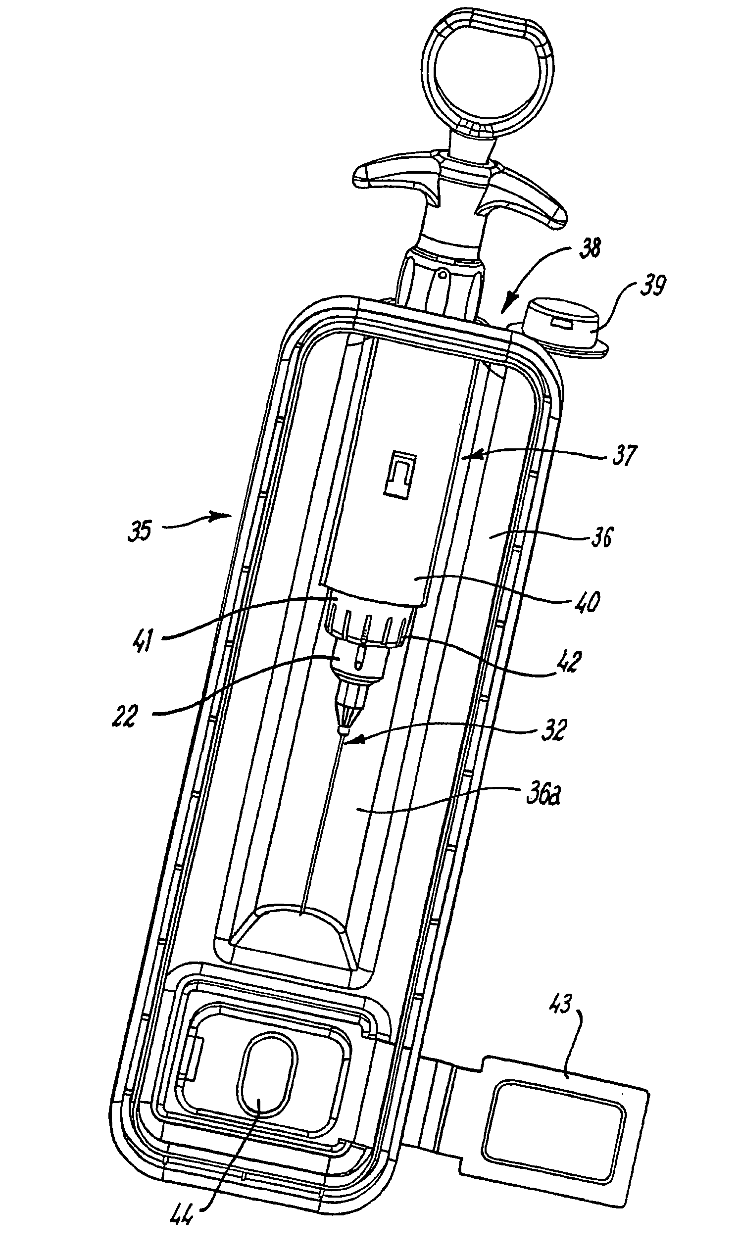
[0007]One object of the present invention is to enable the needle of a syringe to be easily and conveniently removed for disposal whilst being effectively protected within a sleeve to prevent needle-stick injuries but without requiring disposal of the sleeve with the needle.
[0013]With this method the needle can be protected by the sleeve as it is presented to the container opening and the needle can then be removed and deposited in the container without requiring disposal of the sleeve. The needle can therefore be removed and safely discarded easily and conveniently, and the main parts of the syringe, including the sleeve, can then be re-used with a fresh needle and mounting device.
[0021]This arrangement allows the needle to be removed and discarded separately from the sleeve.
[0022]Also, insofar as removal requires only the application of a linear pull-off force, the needle can be detached in a particularly quick and convenient manner notwithstanding the presence of the sleeve.
[0034]In one embodiment, the syringe sleeve has mounted thereon a member movable between release and locking positions whereby in the locking position cooperable configurations on the member and on the barrel interengage to prevent relative longitudinal movement of the member and the barrel and in the release position these configurations are disengaged to permit longitudinal movement.

Problems solved by technology

However, there is the problem of avoiding contact with the needle after use and prior to its presentation to the removal device.
However, there is then the problem of convenient removal and disposal of the covered needle.
With regard to the passageway, most preferably the arrangement is such that this will receive the syringe barrel and the needle, but will not allow complete passage of the syringe sleeve whereby this is retracted as the syringe is inserted.

Method used


Image

  • Safety syringe with re-usable main parts, method for disposal of a needle into a container and container for disposable parts
  • Safety syringe with re-usable main parts, method for disposal of a needle into a container and container for disposable parts
  • Safety syringe with re-usable main parts, method for disposal of a needle into a container and container for disposable parts

Examples


Embodiment Construction

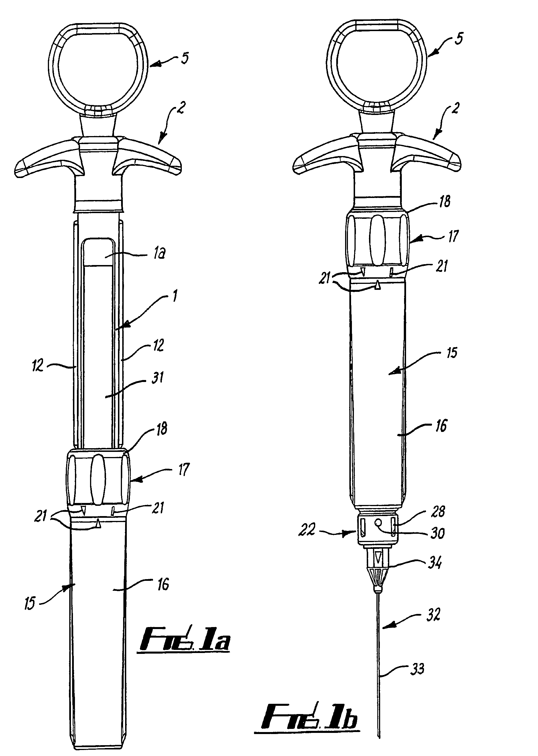
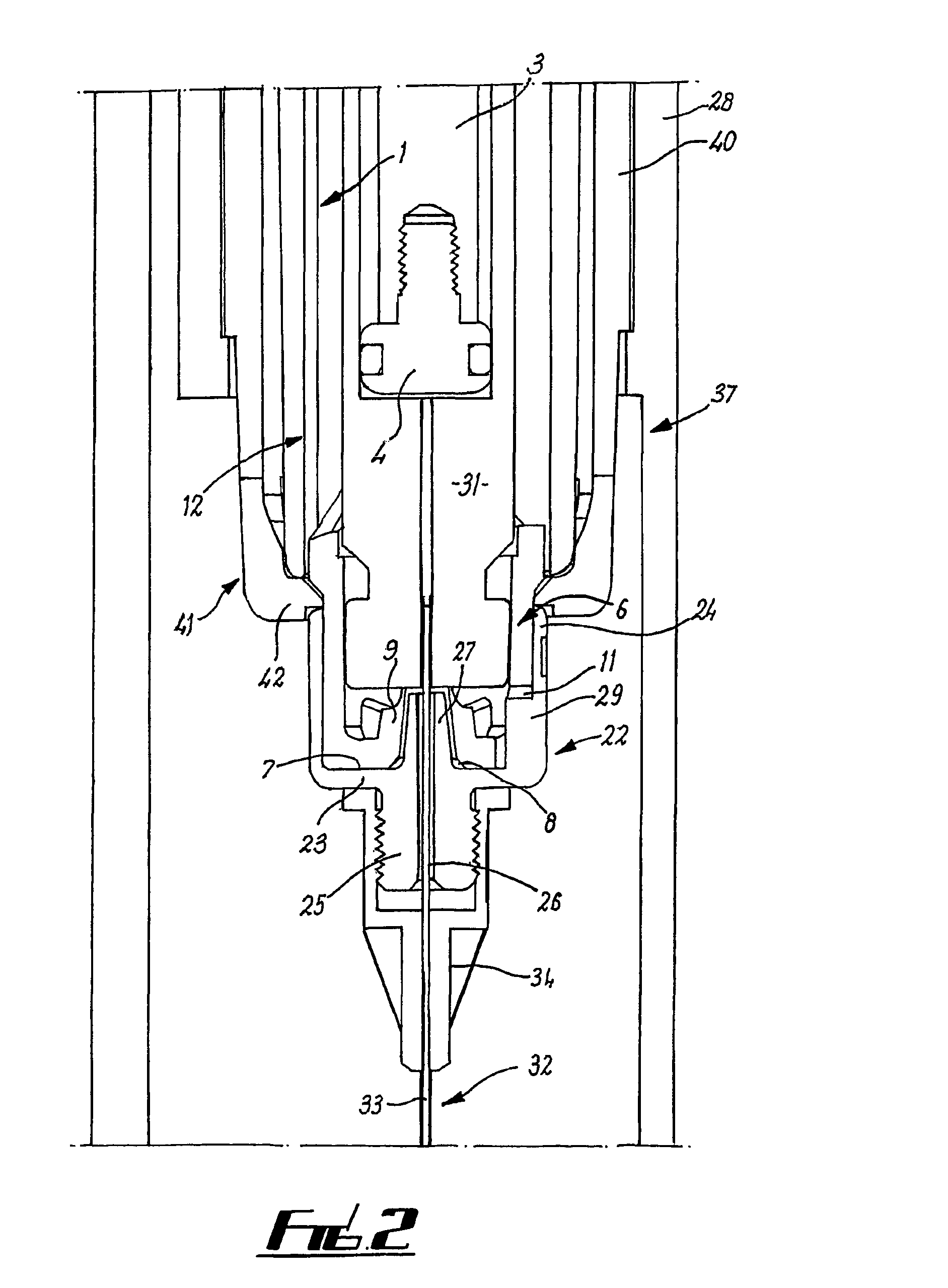
[0050]Referring to FIGS. 1 and 2, a dental syringe has a barrel 1 in the form of a tube of circular cross-section which is open at its rear (distal) end and closed at its forward (proximal) end and has a cut-out side opening 1a.

[0051]The barrel 1 has a finger grip structure 2 attached to the rearward open end, with a plunger 3 extending through this structure 2. The plunger 3 terminates at a forward free end with an enlarged head 4, and at a rearward end with a further finger grip 5.

[0052]At its forward end, the barrel 1 has an integral end portion 6 with a flat radially extending front end face 7 with an axial aperture 8 bounded by a rearwardly projecting tapered structure 9. There is a longitudinal slot 11 running from the end face 7.

[0053]The barrel 1, finger grip structure 2 plunger and finger grip 5 may be formed from stainless steel or plastics which can be disinfected by autoclaving or other technique.

[0054]As shown in FIG. 5, the barrel has diametrically opposed longitudina...


PUM


Abstract

A syringe has a barrel to receive a cartridge. The barrel has a front end portion to which a needle is connected for engagement with the cartridge. At its rear end, the barrel has a plunger mechanism. A sleeve is slidably mounted on the barrel and can be pushed forwards to sheath the needle. The needle is mounted on the barrel via a push-fit mounting device. The needle can be removed for disposal in a container by inserting the syringe into a tube on top of the container so that the protective needle sleeve is pushed back and the needle and mounting device pass through a collar of gripping fingers at an inner end of the tube. The fingers catch behind the mounting device so that this is pulled off to drop into the container with the needle when the syringe is withdrawn from the tube.

Description

BACKGROUND AND SUMMARY OF THE INVENTION[0001]This invention relates to syringes, particularly although not exclusively for dental use, and is more particularly concerned with safe disposal of needles of such syringes.[0002]A conventional dental syringe has a barrel with a plunger mechanism at a rear end and a threaded adaptor to receive a needle at a front end. In use a glass cartridge, which contains an injectable liquid between a rear bung and a front membrane, is inserted into the barrel. A needle having a threaded hub adjacent to its rear end is screwed onto the adaptor so that it penetrates the cartridge membrane, and the plunger mechanism is engaged with the bung at the rear end of the cartridge.[0003]After use, the cartridge and needle are removed and discarded. For safety purposes, the needle may be deposited in a so-called ‘sharps’ container for safe disposal.[0004]In order to avoid needle-stick injuries there have been various proposals for facilitating safe handling of th...

Claims


Application Information

Patent Timeline
Patent Type & Authority Patents(United States)
IPC IPC(8): A61M5/00A61M5/24A61M5/32A61M5/34
CPCA61M5/24A61M5/3205A61M5/3243A61M5/344A61M2005/2414A61M2005/3206
Inventor SEGAL, ALAN JULIAN
Owner ASTEK INNOVATIONS
Learn More