
Laminated film

a technology of laminate film and film layer, applied in the field of laminate film, can solve the problems of large loss of transmission, difficult to control the distribution precisely into the refractive index, unsuitable waveguide for high-speed transmission, etc., and achieve the effects of large information transmission capacity, small light attenuation, and small dispersion

Active Publication Date: 2010-12-14
TORAY IND INC
View PDF20 Cites 0 Cited by
  • Summary
  • Abstract
  • Description
  • Claims
  • Application Information

AI Technical Summary

Benefits of technology

The present invention provides a laminated film that has low transmission loss, excellent heat and humidity resistance, and an arbitrarily-controlled refractive index distribution. The film has a layer structure where the thicknesses of resin layers with the same composition increase or decrease from the side of a surface of the film. This results in a film that is suitable for optical communication and display applications.

Problems solved by technology

However, this optical waveguide is of a step index type (SI type), and thus the waveguide is unsuitable for high-speed transmission.
Additionally, there remains a problem that the loss of transmission is large at the time of bending the waveguide into a large curvature and using the bent waveguide.
However, the GI type optical waveguide is formed by infiltrating and dispersing a sublimable or volatile organic compound, as disclosed in, for example, Patent Document 2; therefore, it is difficult to control the distribution precisely into a refractive index distribution like a square distribution ideal for the GI type optical waveguide, wherein mode distribution is hardly generated.
In a high-temperature and high-humidity environment, the infiltrated and dispersed compound frequently diffuses, thereby causing a problem that the refractive index distribution changes with time.
However, the concentration distribution of the nano particles is not mechanically controlled.
Thus, it is essentially difficult to attain a refractive index distribution high in precision, and there is also a problem that loss based on scattering is large.
However, the conventional laminated films give a large loss resulting from reflection based on the refractive index difference between layers therein, and cannot be applied to optical waveguides.

Method used

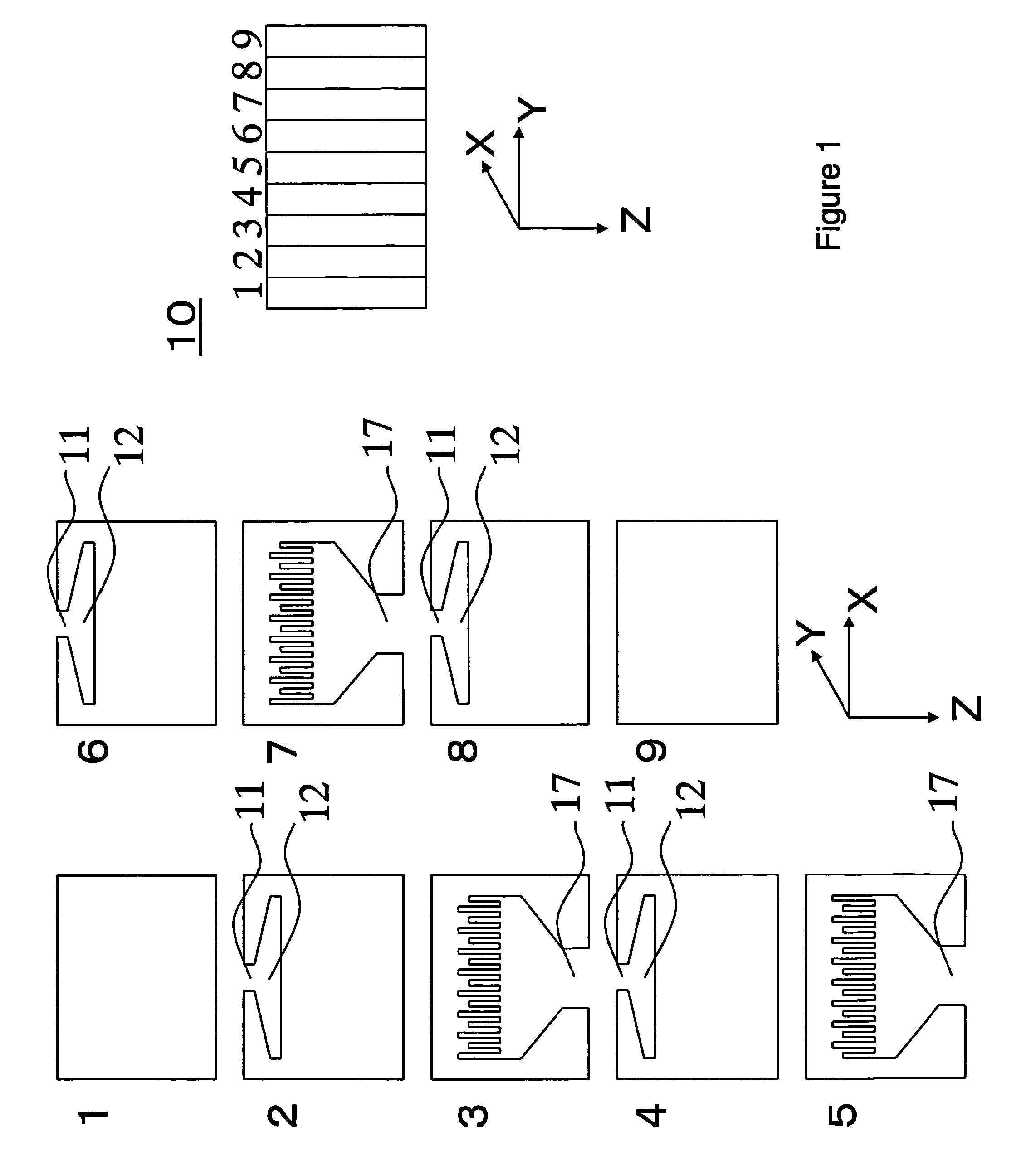
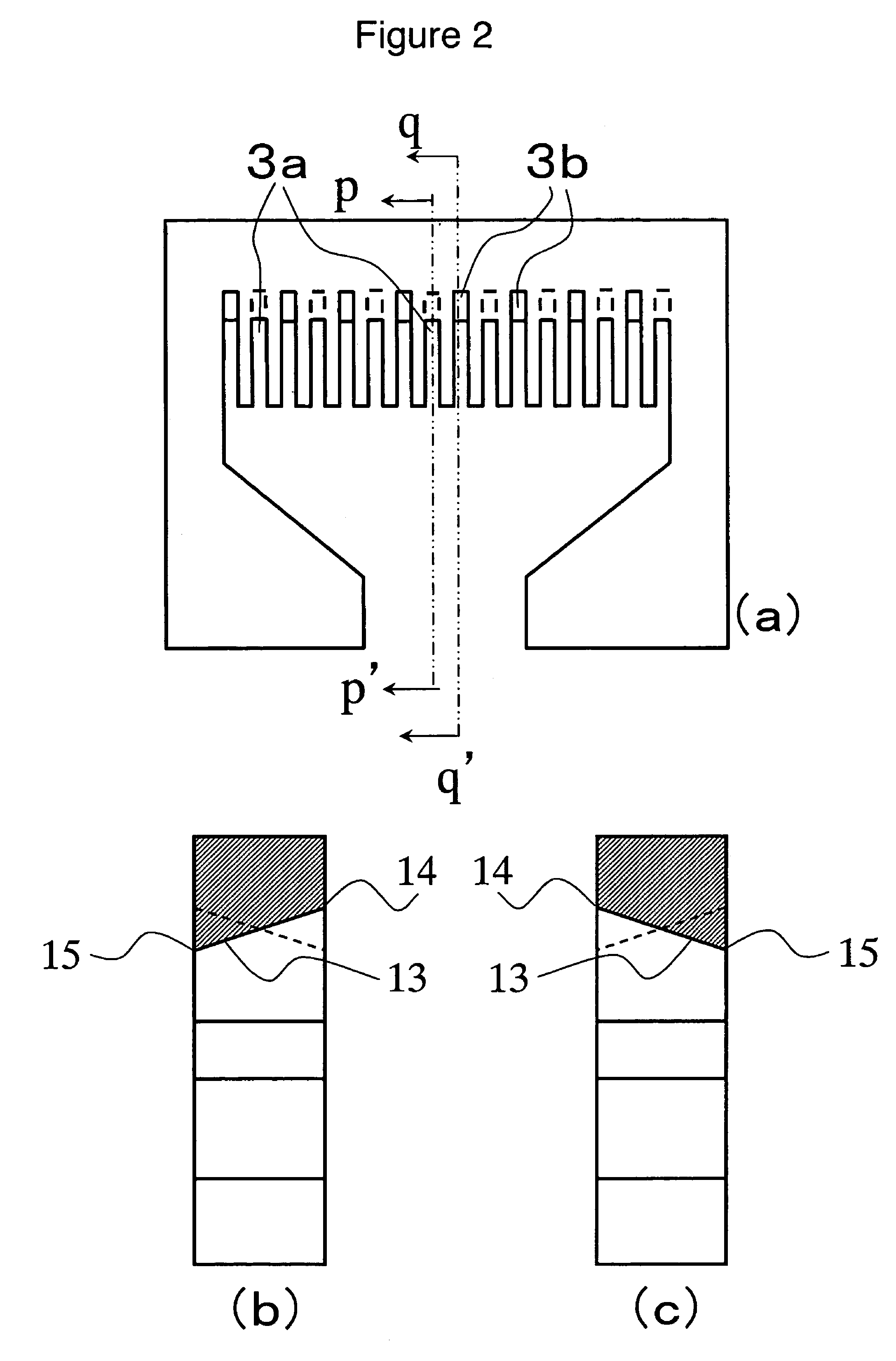
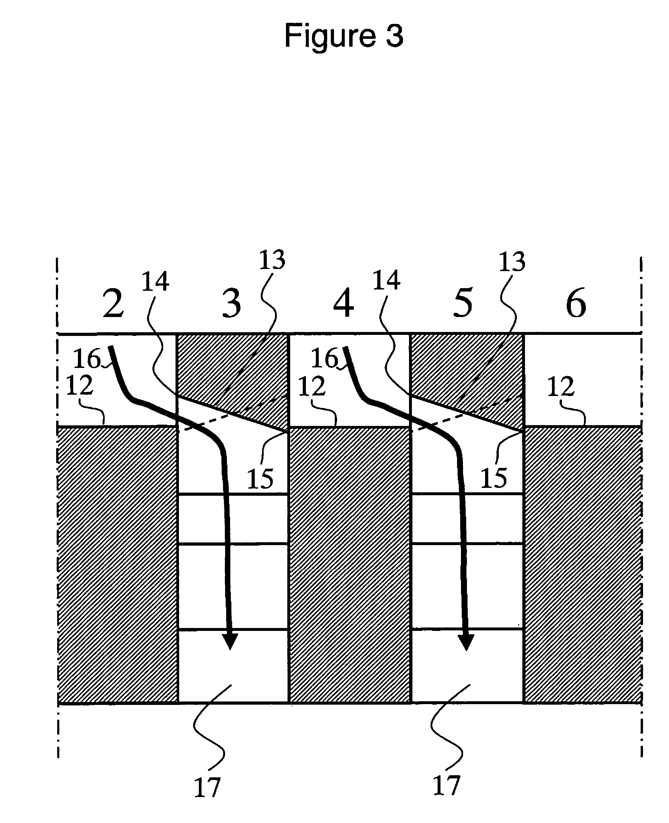

Image

  • Laminated film
  • Laminated film
  • Laminated film

Examples


example 1

[0113]As two thermoplastic resins, the following were used: a thermoplastic resin X: a methacrylic resin (PMMA)

[0114][ACRYPET VH [transliteration], manufactured by Mitsubishi Rayon Co., Ltd.], and

a thermoplastic resin Y: a polycarbonate (PC)

[0115][S-2000, manufactured by Mitsubishi Engineering Plastics Corp.]

[0116]These thermoplastic resins X and Y were each dried, and then the resins were separately supplied into extruders and made into a melted state at 230° C.

[0117]The melted thermoplastic resins X and Y were each passed through a gear pump and a filter, and then the resins were supplied into a feed block for the lamination of 3001 layers, as illustrated in FIG. 1. The thermoplastic resins X and Y were made into a structure wherein: the thicknesses of layers made thereof changed gradually from the sides of the surfaces toward the side of the center; and the thermoplastic resin X layers, the number of which was 1501, and the thermoplastic resin Y layers, the number of which was 15...

example 2

[0123]A laminated film was produced in the same way as in Example 1 except that the shapes of the fine slits in the feed block were changed and the injected amounts of the thermoplastic resins X and Y were adjusted so as to set the lamination ratio (=the ratio by weight) in the whole as follows: X / Y=1.5.

[0124]The thickness of the resultant film was 45 μm.

[0125]In the two surface portions of the resultant film, the thicknesses of the thermoplastic resin X layers were each 27 nm, and those of the thermoplastic resin Y layers were each 3 nm. In the central portion thereof, the thickness of the thermoplastic resin X layer was 3 nm, and that of the thermoplastic resin Y layer was 27 nm. The thicknesses of the thermoplastic resin X layers decreased from 27 to 3 nm from the surface portions toward the central portion while the thicknesses of the thermoplastic resin Y layers increased from 3 to 27 nm from the surface portions toward the central portion. The thickness distribution of the the...

example 3

[0128]The two surfaces of the film of Example 2 were coated with an amorphous fluorine-contained resin (refractive index: 1.34) manufactured by Asahi Glass Co., Ltd. as clads, and then the resin was dried. The thickness of the resultant film was 49 μm.


PUM

PropertyMeasurementUnit
thicknessaaaaaaaaaa
thicknessaaaaaaaaaa
light ray reflectivityaaaaaaaaaa

Abstract

An object of the invention is to provide a laminated film which hardly gives transmission loss based on reflection or scattering, is excellent in heat resistance and humidity resistance, and has an arbitrarily-controlled refractive index distribution. Accordingly, the invention is a laminated film comprising 5 or more laminated resin layers; the thickness of each of the resin layers being from 1 to 100 nm; and the film having a layer structure wherein the thicknesses of resin layers having the same composition A, out of the resin layers, increase or decrease from the side of a surface of the laminated film toward the side of the other surface opposite thereto.

Description

TECHNICAL FIELD[0001]The present invention relates to a laminated film.BACKGROUND ART[0002]Sheet-form optical waveguides are suggested for optical communication / optical circuits, such as an optical cable and an optical waveguide, and for displays, such as a liquid crystal display, a plasma display, an EL display, and a projection screen.[0003]For example, for optical communication / optical circuits, Patent Document 1 discloses a signal transmitting bus wherein light transmitting layers, which receives signal light and then diffuses and transmits the received signal light, and light blocking layers, which blocks the mixing of the signal light between adjacent ones out of the light transmitting layers, are alternately laminated. Such an optical waveguide has advantages that: the amount of crosstalks or electromagnetic noises therefrom is small; the waveguide is easily positioned; and a circuit board can be freely put on and taken off from the waveguide. However, this optical waveguide ...

Claims


Application Information

Patent Timeline
Patent Type & Authority Patents(United States)
IPC IPC(8): B32B7/02B32B7/023B32B27/06
CPCB32B7/02B32B27/06B32B27/08B32B2250/05B32B2250/24B32B2307/306Y10T428/2495B32B2307/7246B32B2307/7265B32B2457/12B32B2457/20Y10T428/24975Y10T428/24942B32B2307/418Y10T428/31786Y10T428/31797Y10T428/31848Y10T428/3154B32B7/023B82B3/00B82Y40/00
Inventor OSADA, SHUNICHIHOSOKAWA, HIROFUMITSUNEKAWA, TETSUYA
Owner TORAY IND INC
Learn More