Switch

a technology of switch and contact structure, which is applied in the field of switches, can solve the problems of high probability of loss of insulation between switches, difficulty in working, and difficulty in repairing switches, and achieve the effects of suppressing the increase of the occupational area of fixed contacts on the board, facilitating work, and high precision

Inactive Publication Date: 2010-12-14
OMRON AUTOMOTIVE ELECTRONICS CO LTD
View PDF34 Cites 9 Cited by
  • Summary
  • Abstract
  • Description
  • Claims
  • Application Information

AI Technical Summary

Benefits of technology

[0010]The present invention has been implemented to solve the above problem, and has an object to provide a switch that can prevent detraction of the insulating performance of fixed contacts and facilitate the design, manufacturing and assembling work and can be miniaturized.
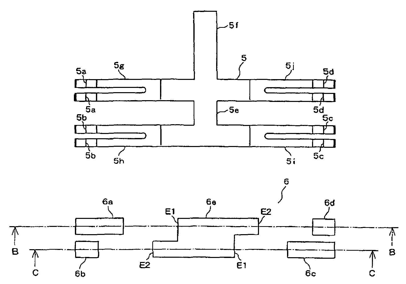
[0012]In the above construction, even when the second to fifth fixed contacts are not provided at positions which are far away from the right and left sides of the first fixed contact, the insulating interval between the first fixed contact and each of the second and fourth fixed contacts which are nearer to the first fixed contact than the third and fifth fixed contacts can be increased. Therefore, the insulation between the first fixed contact and each of the second and fourth fixed contacts can be prevented from being detracted due to adhesion of electrically conductive powder to the surface of the insulator between the first fixed contact and the second or fourth fixed contact, the powder being generated by abrasion of the first fixed contact and the second and fourth fixed contacts due to arc discharge occurring when the first fixed contact and the second or fourth fixed contact are opened or closed. Furthermore, the insulation due to adhesion of other foreign matters having electrical conductivity to the surface of the insulator between the first fixed contact and the second or fourth fixed contact can be also prevented from being detracted. Furthermore, high precision is not required for the design, manufacturing and assembling works of the movable contact, the fixed contacts and the respective parts such as the movable piece, the boards, etc., and thus the works can be facilitated. Still furthermore, increase of the occupation area of the fixed contacts on the board can be suppressed, so that the switch can be miniaturized.
[0014]In the above construction, the second and fourth fixed contacts and the insulator between the first fixed contact and the second or fourth fixed contact are arranged obliquely in the sliding direction of the movable contact, so that the interval concerned can be more increased. Therefore, even when electrically-conductive or electrically-non-conductive foreign matters adhere to the surface of the insulator between the first fixed contact and the second or fourth fixed contact, the foreign matters are prevented from moving from one insulator surface to the other insulator surface in connection with the sliding movement of the movable contact, and thus the insulating performance between the first fixed contact and the second or fourth fixed contact and the contact reliability between the fixed contact and the movable contact can be prevented from being detracted.
[0020]As described above, even when the other fixed contacts are not provided so as to be far away from the right and left sides of the earth fixed contact, the insulating interval between the earth fixed contact and the manual-up / down fixed contact nearer to the earth fixed contact than the automatic-up / down fixed contact point can be increased, thereby preventing detraction of the insulation due to adherence of foreign matters having electrical conductivity to the surface of the insulator between the earth fixed contact and the manual-up / down fixed contact. Furthermore, high precision is not required for the design, manufacturing and assembling works of the movable contact and the fixed contacts and respective parts such as the movable piece, the boards, etc., and thus the works can be facilitated. Furthermore, the increase of the occupational area of the fixed contacts on the board can be suppressed, and the power window switch can be miniaturized.
[0021]According to the present invention, even when the second to fifth fixed contacts are not provided to the positions which are far away from the right and left sides of the first fixed contact, the insulating interval between the first fixed contact and each of the second and fourth fixed contacts which are nearer to the first fixed contact than the third and fifth fixed contacts can be increased. Therefore, the detraction of the insulation between the first fixed contact and the second or fourth fixed contact can be prevented, the design, manufacturing and assembling works of respective contacts and respective parts can be facilitated, and also the occupational area of the fixed contacts on the board can be suppressed from being increased, so that the switch can be miniaturized.

Problems solved by technology

Furthermore, other foreign matters having electrical conductivity such as water drop or the like may adhere to the surface of the insulator between the fixed contacts 56a, 56c, 56e, so that the insulation therebetween may be lost with high probability.
Still furthermore, high precision is required for design, manufacturing and assembling of the contacts 55a to 55d, 56a, 56c, 56e, etc. and respective parts such as the movable piece, the board, etc., and thus the working is difficult.
Such a problem may likewise occur in the contact structures of the patent documents 1, 2.

Method used


Image

  • Switch
  • Switch
  • Switch

Examples


Embodiment Construction

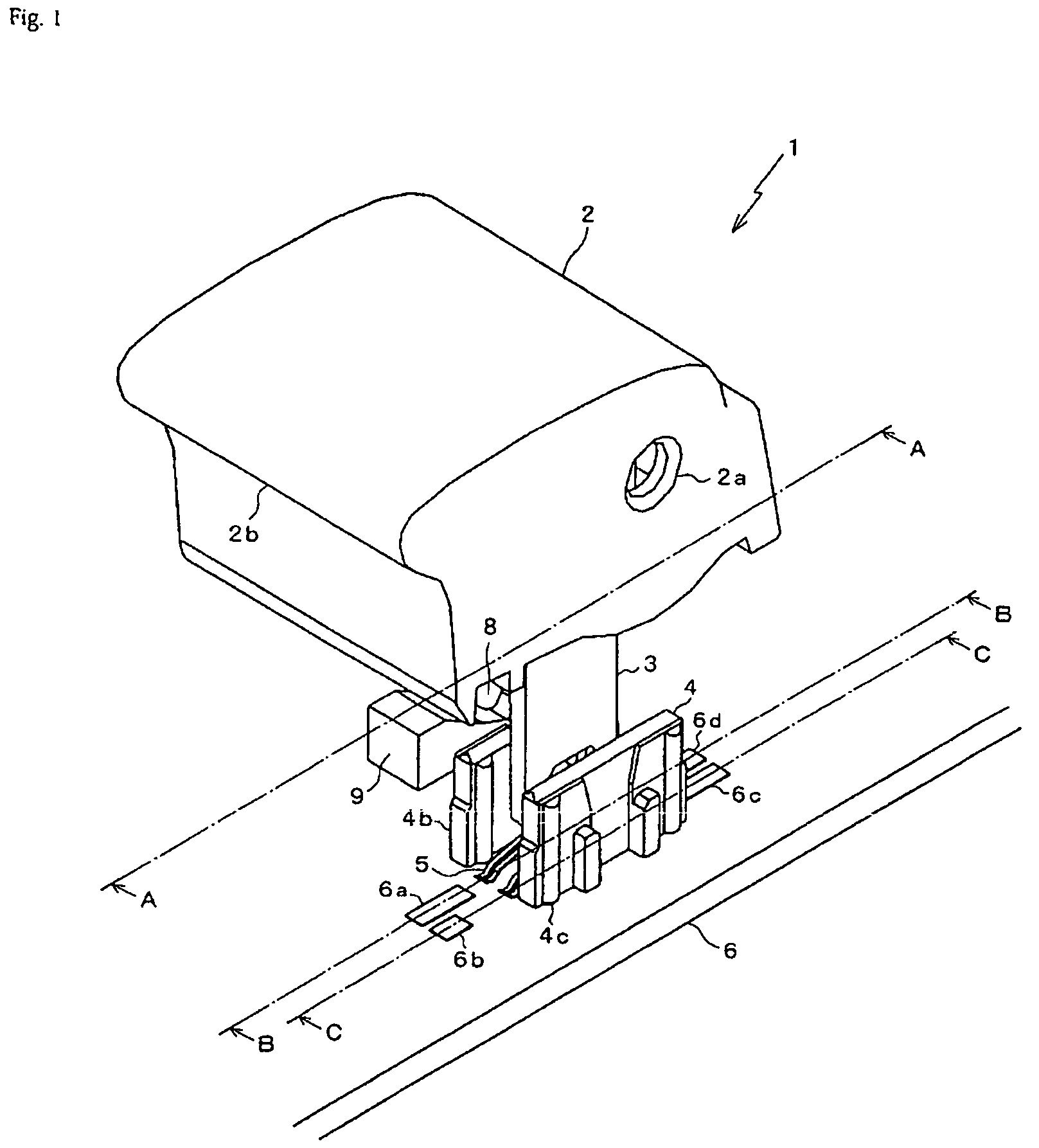
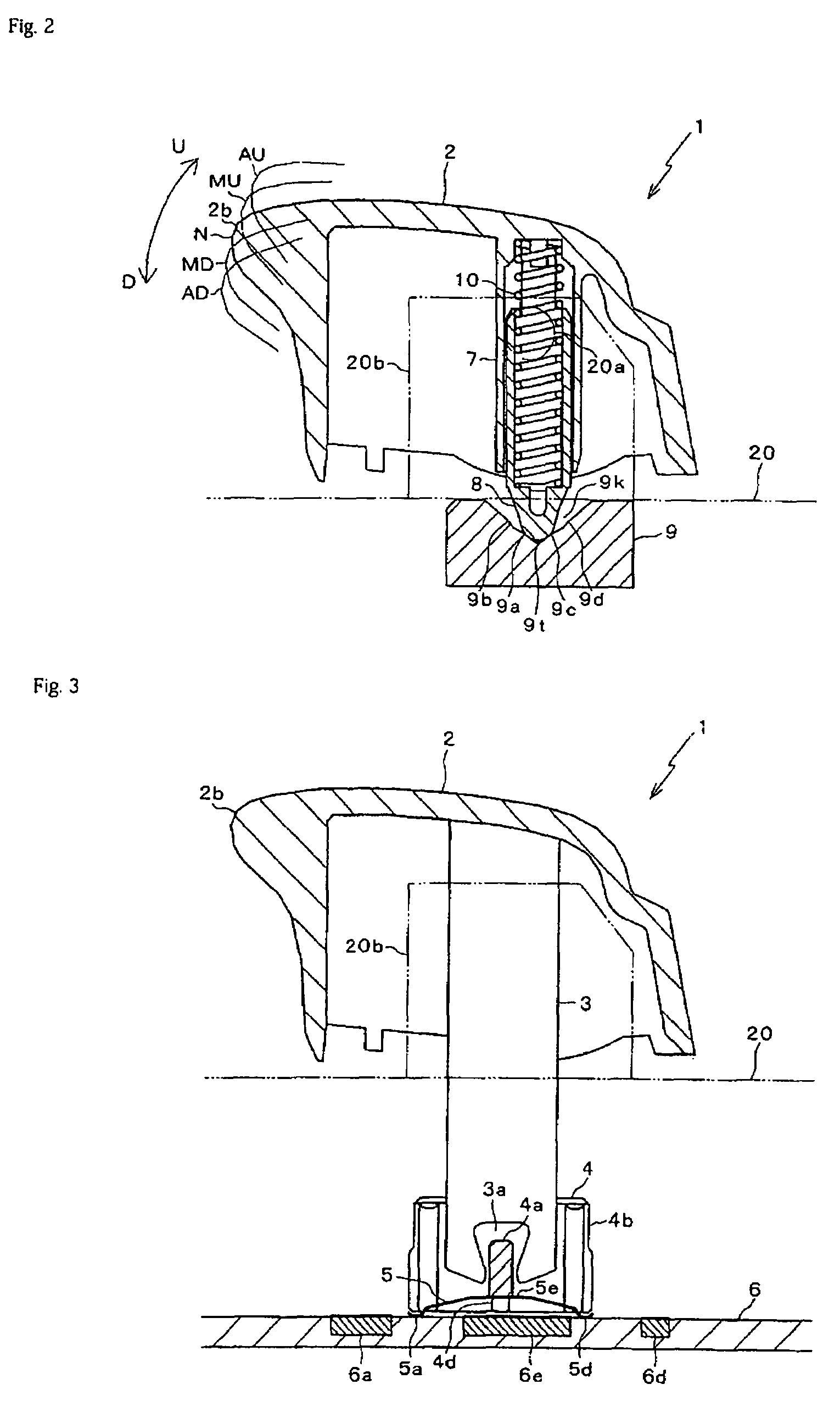
[0038]FIG. 1 is a perspective view showing a power window switch 1. FIG. 2 is a A-A cross-sectional view of FIG. 1 of the power window switch 1. FIG. 3 is a B-B cross-sectional view of FIG. 1 of the power window switch 1. FIG. 4 is a C-C cross-sectional view of FIG. 1 of the power window switch 1. The power window switch 1 serves to manipulate the power window at the side of the driver's seat of the vehicle, for example, and it is provided to an in-vehicle mount type switch module 100 as shown in FIG. 14. The switch module 100 is secured to an arm rest of the door of the driver's seat or the like. Parts other than the knob 2 of the power window switch 1 are disposed in lock-engaged upper and lower cases 20, 30 of the switch module 100.

[0039]Shafts 20a provided on both the side surfaces of a cylinder portion 20b of the upper case 20 is engagedly fitted in holes 2a provided to both the side surfaces, whereby the knob 2 is secured to the upper portion of the upper case 20 so as to be r...


PUM


Abstract

A switch which can prevent detraction of insulation of fixed contacts and facilitate design, manufacturing and assembling works and can be miniaturized is disclosed. In a power window switch, an earth fixed contact 6e is provided at the center and a manual-up fixed contact, an automatic-up fixed contact, a manual-down fixed contact, and an automatic-down fixed contact are arranged in the right-and-left direction are provided as fixed contact on a board along which movable contacts provided to a movable piece are slid by reciprocating motion of the movable piece in the right-and-left direction. The manual-up / down fixed contacts are nearer to the earth fixed contact than the automatic-up / down fixed contacts. The earth fixed contact is designed so that side portions of the earth fixed contact which are near to the manual-up / down fixed contacts are concaved with respect to side portions near to the automatic-up / down fixed contacts.

Description

BACKGROUND OF THE INVENTION[0001]1. Field of the Invention[0002]The present invention relates to a switch whose electrical connection state is switched by a linear reciprocating motion of a movable piece.[0003]2. Description of Related Art[0004]A switch used as a power window switch to be mounted in a vehicle or the like is provided with a movable contact and a fixed contact. The movable point is slid on the fixed contact in connection with a linear reciprocating motion of a movable piece and comes into contact with or separates from the fixed contact, so that it is kept to a close state or an open state (electrically conductive state or electrically non-conductive state).[0005]FIG. 15 is a perspective view showing an example of a related art power window switch. A power window switch 51 serves to operate a power window at the side of the driver's seat of a vehicle, and it is provided to a switch module (not shown). A knob 52 is supported in U, D directions by inserting shafts (not ...

Claims


Application Information

Patent Timeline
Patent Type & Authority Patents(United States)
IPC IPC(8): H01H9/26
CPCH01H23/003H01H23/164H01H15/04H01H23/04H01H2021/225H01H2300/01H01H9/00H01H9/24
Inventor KAKUNO, HIDEYO
Owner OMRON AUTOMOTIVE ELECTRONICS CO LTD
Why Eureka
Try Eureka